Table of Contents
Advertisement
Quick Links
Advertisement
Table of Contents

Related Manuals for Armstrong Medical AquaVENT FD140i


Summary of Contents for Armstrong Medical AquaVENT FD140i
- Page 1 AquaVENT FD140i ® User Manual, English...
- Page 2 Guidance Guidance WARNING Correct operation of this device is described in this User Manual and on other documents or materials enclosed or provided by the manufacturer. It should only be assembled, operated, maintained and repaired according to such information. The device must be checked prior to each clinical use to verify that it is operable and meets the user’s requirements for delivery of therapy to patients.
- Page 3 Contents AquaVENT® FD140i, User Manual, English Issue 05...
-
Page 4: Table Of Contents
Contents Contents Page No. 1. Introduction 1.1 About this manual 1.2 Indications for use 1.3 Contraindications 1.4 Adverse eff ects 1.5 General safety precautions 1.6 Limitation of liability 1.7 Copyright 1.8 Service life 1.9 Warranty 2. AquaVENT® FD140i overview 2.1 Principle of operation 14-16 2.2 Device layout 2.3 Therapy modes technical specifi cation... - Page 5 Contents Page No. 5. Alarms and notifi cations 5.1 Alarm indicator button 5.2 Alarm acknowledgement 5.3 Muting alarm audio 5.4 Alarm volume adjustment 52-53 5.5 CPAP low pressure alarm fl ow settings override 54-57 5.6 Alarm types 5.7 Alarms settling period 6.
-
Page 6: Introduction
1 Introduction AquaVENT® FD140i, User Manual, English Issue 05... -
Page 7: About This Manual
The AquaVENT® FD140i must only be used by qualifi ed healthcare professionals trained in the operation of the device. Armstrong Medical Ltd. reserves all rights to further develop and alter AquaVENT® FD140i in the interest of technical progress and patient safety. -
Page 8: Indications For Use
Introduction 1.2 Indications for use AquaVENT® FD140i is a gas fl ow driver, delivering an air and oxygen mixture at 21-100%. It is a clinical respiratory therapy device which assists respiration using continuous positive airway pressure (CPAP) and high fl ow oxygen therapy (HFOT) in patients in a hospital setting. Such patients must be medically- indicated by a healthcare professional for the respective therapy once assessed as conscious and breathing spontaneously and not at signifi cant risk of conditions of exacerbation caused by the therapy or at risk of a prolonged apnoeic event. -
Page 9: Contraindications
Introduction 1.3 Contraindications This section details some, but not all conditions, which make the following therapies inadvisable: CPAP • Respiratory arrest or unstable cardiorespiratory status • Reduced consciousness • Apnoea • Inability to protect airway • Extremely anxious patient • Facial trauma / burns •... -
Page 10: Adverse Eff Ects
Introduction 1.4 Adverse eff ects The most common adverse eff ects during CPAP therapies are face mask or helmet or gas fl ow/pressure related. Some patients may experience claustrophobia due to the mask, nasal congestion, rhinitis or a runny nose. To minimise these adverse eff ects ensure that: •... -
Page 11: General Safety Precautions
Introduction 1.5 General safety precautions To ensure safe operation of AquaVENT® FD140i , all precautions contained within this chapter must be adhered to, in addition to all other warnings, cautions and notes dispersed throughout the User Manual. WARNING Alerts you to a situation which may cause patient or user injury CAUTION Explains measures for the eff ective use of the device NOTE... -
Page 12: Limitation Of Liability
AquaVENT® FD140i is 10 years from the date of delivery to the hospital. 1.9 Warranty The warranty conditions correspond with Armstrong Medical’s terms and conditions at the time of purchase. Warranty will be valid for 2-years from the date of delivery to the hospital and will cover defects in parts and labour that arise when the repaired device is used correctly and in-line with this User Manual. -
Page 13: Aquavent Fd140I Overview
AquaVENT® FD140i Overview 2 AquaVENT FD140i ® Overview AquaVENT® FD140i, User Manual, English Issue 05... -
Page 14: Principle Of Operation
AquaVENT® FD140i Overview 2.1 Principle of operation AquaVENT® FD140i is an electronic gas fl ow driver which delivers an adjustable blend of medical air and oxygen to the patient via an attached breathing circuit. The device has six preset respiratory therapies; •... - Page 15 AquaVENT® FD140i Overview AquaVENT® FD140i, User Manual, English Issue 05...
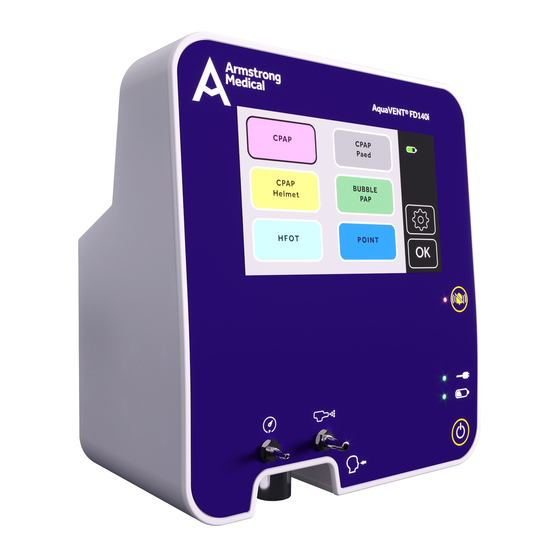
- Page 16 AquaVENT® FD140i Overview 2.2 Device layout Item Description Pressure measurement port Respiratory gas outlet Nebuliser port Touch screen Alarm mute button Mains power connection indicator Battery status indicator Power on/off button Refer to instruction manual/booklet Mains power inlet USB connector Handle Fan outlet Fixation claw...
-
Page 17: Therapy Modes Technical Specifi Cation
AquaVENT® FD140i Overview 2.3 Therapy modes technical specifi cation CPAP Helmet BUBBLE- CPAP HFOT POINT (Paed) CPAP Mode Interface screen colour Purple Grey Yellow Green Light blue Dark blue Flow range (L/min) 20-140 10-70 40-140 2-20 2-70 10-80 Default fl ow (L/min) Oxygen range (%) 21-100 21-100... -
Page 18: Device Interface
AquaVENT® FD140i Overview 2.4 Device interface Front panel icons and indicator lights Description 1. Power source indicators AC mains power supply is connected when indicator light is illuminated Running on internal battery when indicator light is illuminated solid green Internal battery is charging when indicator light is fl ashing green Internal battery level is ≤... -
Page 19: Touch Screen Icons
AquaVENT® FD140i Overview Touch screen icons Description 1. Screen lock Screen Locked 2. Power supply and battery charge indication Device unplugged from mains power Internal battery level-percentage charged (alternates between battery icon and unplugged icon) ...% Battery level at 20% or below Battery charging Charging 3. -
Page 20: Device Setup
Device Setup 3 Device Setup AquaVENT® FD140i, User Manual, English Issue 05... -
Page 21: Unpacking
Device Setup 3.1 Unpacking When unpacking AquaVENT® FD140i, the following parts should be present: • AquaVENT® FD140i device • Power lead • User Manual • Technical Manual (optional) If all the parts listed above are not present, please contact the manufacturer. NOTE The protective packaging containing the device should be retained for when the device is being transported back to the manufacturer for service or repair. - Page 22 Device Setup WARNING • The device should be mounted on approved pole stands only with a load capacity of at least 10Kg. • Do not mount the device at a height greater than 1400mm measured from the base of the device to the fl oor.
-
Page 23: Power Supply
Device Setup 3.3 Power supply Connecting to Mains Supply Connect the original power lead to the mains power inlet on the back of the device and plug into the mains supply. The AquaVENT® FD140i should be used with a mains supply voltage ranging from 100 - 240VAC at 50 - 60Hz only. -
Page 24: Battery Powered Operation
Device Setup Battery powered operation An internal battery is included in AquaVENT® FD140i which ensures a continuous power supply when mains power is disconnected or disrupted. When fully charged, the internal battery operates for a minimum of 60 minutes under typical therapy operation. When AquaVENT® FD140i starts using the internal battery as its power source, you are notifi ed by the battery status indicator on the front panel. -
Page 25: Connecting To Gas Supply
Device Setup 3.4 Connecting to gas supply Medical Oxygen (O ) and Medical air (AIR) is connected to the device via the NIST connectors positioned on the back of the device. NOTE: Prior to commencing patient therapy the user must verify that peak fl ows of up to 140L/min for both Air and Oxygen can be achieved with a supply pressure ranging from 270 to 600 kPa. -
Page 26: Breathing Circuit Set-Up
Device Setup 3.7 Breathing circuit set-up AquaVENT® FD140i should be used with Armstrong Medical breathing circuits and components. For more information refer to Appendix 2, “Accessories”. For specifi c therapy mode fl ow and pressure ranges please refer to “Therapy Mode Technical Specifi cations“ table in Chapter 8. - Page 27 Device Setup AquaVENT® FD140i has six available modes; CPAP, CPAP Paed., CPAP Helmet, Bubble-PAP, HFOT and POINT®. Breathing circuit arrangements for each mode are outlined in this chapter. CPAP Continuous Positive Airway Pressure (CPAP) therapy maintains a target positive airway pressure during inspiration and expiration in the spontaneous breathing patient.
- Page 28 Device Setup CPAP Paed. The CPAP Paediatric mode is, in principle, the same as adult CPAP but delivers gas fl ow within a suitable range for paediatric patients. Suggested assemblies of the CPAP breathing system: FD140i Breathing Filter Disconnect T-piece for oxygen Connect to analyser humidifi cation...
- Page 29 Device Setup Helmet CPAP AquaVENT® FD140i supports non-invasive ventilation by means of a CPAP helmet. Suggested assemblies of the Helmet CPAP breathing system: FD140i Disconnect Breathing Filter Option: Direct connection to helmet Safety over-pressure T-piece for valve oxygen analyser Pressure Pressure monitoring line monitoring line...
- Page 30 Device Setup High Flow Oxygen Therapy (HFOT) High Flow Oxygen Therapy is a form of respiratory support where high fl ow rates (20-70 l/min) of Oxygen/Air mixture is delivered to the patient. Suggested assemblies of the HFOT breathing system: FD140i Disconnect Connect to humidifi cation...
- Page 31 Device Setup POINT® POINT® (Peri-Operative Insuffi atory Nasal Therapy) delivers humidifi ed high fl ow nasal therapy to support the patient during the peri-operative period. Suggested assemblies of the POINT® breathing system: FD140i Disconnect Connect to humidifi cation chamber outlet Breathing Filter Heated...
- Page 32 Device Setup Bubble-PAP Bubble-PAP provides a safe, consistent and accurate method of delivering humidifi ed respiratory support to spontaneously breathing patients from birth weight up to 10kg. The therapy prevents airway closure and maintains functional residual capacity. Suggested assembly of the Bubble-PAP breathing system: FD140i Disconnect Connect to humidifi cation...
-
Page 33: Using The Aquavent Fd140I
Using the AquaVENT® FD140i 4 Using the AquaVENT FD140i ® AquaVENT® FD140i, User Manual, English Issue 05... -
Page 34: Powering On The Device
Using the AquaVENT® FD140i 4.1 Powering on the device AquaVENT® FD140i can be powered on by pressing the ON/OFF button. NOTE: The device runs an automatic system test each time it is switched on. Please refer to “Self Check” section for details. WARNING Do not power on the device if a patient is already connected to an attached breathing circuit. -
Page 35: Automatic Switch-Off Due To Discharged Battery
Using the AquaVENT® FD140i 4.3 Automatic switch-OFF due to discharged battery To avoid damage to the internal rechargeable battery by deep discharging, when reaching the power off threshold (battery level indicator at 0%) the device powers off all electric and pneumatic functions and displays the following message for 120 seconds: During this 2 minute period, you can reconnect AquaVENT®... -
Page 36: Self Check
The system test starts automatically after the ON/OFF button is pressed and lasts for approximately 10 seconds. During this period an Armstrong Medical logo is presented whilst the system test is running in the background. If there are any issues/faults the Self Check Results screen is shown. If there are no issues/ faults found during the system test the device will present the “OXYGEN Sensor Calibration”... -
Page 37: Oxygen Sensor Calibration
Using the AquaVENT® FD140i 4.5 Oxygen sensor calibration After the self check the following “OXYGEN Sensor Calibration” menu is presented. If calibration of the sensor is required, press “Yes”, if not required select “No”. The device’s paramagnetic O sensor is sensitive to movement. -
Page 38: Therapy Selection Menu
Using the AquaVENT® FD140i 4.6 Therapy mode selection menu The “Therapy Mode Selection” menu presents the six therapy modes available. These modes are CPAP, CPAP Paed., CPAP Helmet, BUBBLE-PAP, HFOT and POINT®. Select the desired mode by touching the relevant Therapy Mode Button and press OK to proceed. In the example shown below CPAP has been selected. -
Page 39: Flow Settings Menu
Using the AquaVENT® FD140i 4.7 Flow settings menu The fl ow settings menu allows you to set the medical air fl ow rate and the concentration of oxygen delivered to the patient. CPAP mode is used as an example. Flow rates are selected using the pointer icon (1) and the +/- (2) buttons for fi ne adjustment. The maximum and minimum values, for the selected therapy, are indicated with the triangular markers (3). -
Page 40: Alarm Settings Menu
Using the AquaVENT® FD140i 4.8 Alarm settings menu The alarm settings menu allows the user to specify when patient alarms will activate. Using the pointers and +/- buttons the user can set the alarms to the desired setting for: • CPAP pressure •... -
Page 41: General Settings Menu
Using the AquaVENT® FD140i 4.9 General settings menu The general settings menu can be accessed via the general settings button. Use the return button to return to the previous menu. General Settings Button Return Button The General Settings Menu allows adjustment to time, date, alarm volume, touch tone volume, screen brightness and language settings. -
Page 42: Therapy Menu
Using the AquaVENT® FD140i 4.10 Therapy menu The Therapy menu allows the user to: • Monitor the patient’s respiratory activity in real time • View selected fl ow levels and access fl ow settings • Switch on or off the nebuliser gas fl ow •... - Page 43 Using the AquaVENT® FD140i Patient respiratory rate and CPAP pressure display window The CPAP pressure displayed in (item 1) is the average Patient Pressure over a 7 seconds period and displayed in cmH The RR is an average value of the previous 3 calculated RR rates. (If no breath is detected for 10 seconds, the RR value will start to be updated to refl ect the low RR as a live calculated value.) The patient respiratory live trace (item 2) presents CPAP pressure and respiratory rate in real time over 7.1 seconds.
-
Page 44: Starting Therapy
Using the AquaVENT® FD140i 4.11 Starting therapy When the user is satisfi ed with the therapy setup, start therapy by pressing the Start therapy button, located on the side bar menu. CPAP mode is used as an example. Start therapy button When the Start therapy button is pressed the user must confi rm that it is their intention to start therapy via the confi rm action window. -
Page 45: Stopping Therapy
Using the AquaVENT® FD140i 4.12 Stopping therapy To stop therapy press the Stop therapy button, located on the side bar menu. CPAP mode is used as an example. Stop therapy button When the Stop therapy button is pressed the user must confi rm that it is their intention to stop therapy via the confi rm action window. - Page 46 Using the AquaVENT® FD140i 4.13 Using with a nebulising system AquaVENT® FD140i can be used in conjunction with a jet nebuliser to add medical aerosol to the breathing circuit during therapy. The nebuliser function cannot be used when therapy is not active. For more information on approved nebulisers refer to section 11.2 Appendix 2,”Accessories”.
- Page 47 Using the AquaVENT® FD140i When active, the nebuliser function adds medical air to the breathing circuit. Consequently, to provide the patient with the selected O concentration, the gas mixer settings adjust automatically when the nebuliser function is switched on. The nebuliser requires a therapy gas fl ow rate of at least 10L/min to operate.
-
Page 48: Touch Screen Unlock
Using the AquaVENT® FD140i 4.14 Touch screen unlock When the screen has not been touched for 30 seconds the screen will lock and the unlock button will appear on the side bar menu. Unlock Button Side Bar Menu To unlock the screen press the Unlock Button then confi rm action by selecting the confi rm button. AquaVENT®... -
Page 49: Alarms And Notifi Cations
Alarms and Notifi cations 5 Alarms and Notifi cations AquaVENT® FD140i, User Manual, English Issue 05... -
Page 50: Alarm Indicator Button
Alarms and Notifi cations 5.1 Alarm indicator button When an alarm is active the Alarm Indicator Button (1) appears on the touch screen . T he colour of the Alarm Indicator Button indicates the alarm priority; red is for medium priority alarms and yellow is for low priority alarms. -
Page 51: Muting Alarm Audio
Alarms and Notifi cations 5.3 Muting alarm audio In therapy alarm Alarm audio is muted by pressing the Alarm Audio Mute Button on the device front panel (5). Pressing this button will activate a confi rmative action window. When this action is confi rmed, the alarm audio will mute for two minutes. -
Page 52: Cpap Low Pressure Alarm Fl Ow Settings Override
Alarms and Notifi cations 5.5 CPAP Low Pressure Alarm (P Min) fl ow settings override In the event of a Low Pressure Alarm (P Min) in CPAP mode, the fl ow override function becomes available. This is indicated by a yellow border around the fl ow settings button. Yellow border Low pressure alarm If the fl ow settings button is pressed when the yellow border is present , the CPAP Flow Setting Override... - Page 53 Alarms and Notifi cations When the fl ow override function is active the yellow border around the fl ow settings button will fl ash. Yellow border-fl ashing NOTE: If the increased fl ow removes the P Min alarm condition , the “Alarm Acknowledge” P Min Alarm notifi cation appears at the indicator button.
-
Page 54: Alarm Types
Alarms and Notifi cations 5.6 Alarm types The following table identifi es all alarm types included in the AquaVENT® FD140i along with alarm condition and corresponding corrective action. Alarm identifi cation numbers (ID) and alarm priorities are also listed. Alarm Alarm Alarm Alarm Condition... - Page 55 Alarms and Notifi cations Alarm Alarm Alarm Alarm Condition Corrective Action Notes Message ID No. Priority If recalibration does Patient Pressure sensor Calibration not clear the alarm, Medium calibration cannot be Recalibrate device PP Sensor return the device to an retrieved approved service centre Battery not fi tted or...
- Page 56 Alarms and Notifi cations Alarm Alarm Alarm Alarm Condition Corrective Action Notes Message ID No. Priority Patient pressure is less Evaluate low pressure alarm P Min alarm does not P Min Medium than applied P Min alarm settings and increase pressure activate in HFOT or limit setting if appropriate...
-
Page 57: Alarms Settling Period
Alarms and Notifi cations Alarm Alarm Alarm Alarm Condition Corrective Action Notes Message ID No. Priority Have device serviced by Fan Defect Medium Technical failure authorised technician Restart therapy. If fault Sensor AIR continues, recalibrate device Medium Technical failure Defect or return the device to an approved service centre Restart therapy. -
Page 58: Maintenance And Repair
6 Maintenance and Repair AquaVENT® FD140i, User Manual, English Issue 05... -
Page 59: Repair
With regular servicing, the expected service life of an AquaVENT® FD140i is 10 years. For more information about maintenance, please refer to AquaVENT® FD140i Technical Manual. The AquaVENT® FD140i should be serviced by an authorised Armstrong Medical service centre according to the following schedule from the fi rst date of use:... -
Page 60: Cleaning And Decontamination
Cleaning and Decontanimation 7 Cleaning and Decontamination AquaVENT® FD140i, User Manual, English Issue 05... - Page 61 Cleaning and Decontanimation 7.1 Cleaning Cleaning and Decontamination Before cleaning, ensure that the device is powered OFF and that the mains power lead is removed and kept separate from cleaning solutions. Use only mild disinfectant detergents applied to a soft cloth. Wipe only the external surfaces of the device.
-
Page 62: Technical Specifi Cations
Technical Specifi cations 8 Technical Specifi cations AquaVENT® FD140i, User Manual, English Issue 05... - Page 63 Technical Specifi cations 8.1 Technical specifi cations Gas supply Oxygen supply (O ) pressure range 270 to 600 kPa (40 to 87 PSI) Oxygen supply (O ) max. over pressure 1000 kPa (145 PSI) Oxygen supply (O ) fl ow rate 140L/min maximum Oxygen supply (O ) quality...
- Page 64 Technical Specifi cations Alarms Type of Alarm Visual and Audible Alarm volume range 45.5 dBA to 86.5 dBA Alarm audio mute duration 120s Noise levels Peak sound pressure (no alarm state) 54.5dBA Peak sound pressure (alarm state) 86.5dBA Display Screen type Colour TFT LCD Screen diagonal 7.0 inch...
-
Page 65: Therapy Modes Technical Specifi Cation
Technical Specifi cations 8.2 Therapy modes technical specifi cation CPAP Helmet BUBBLE- CPAP HFOT POINT (Paed) CPAP Mode Interface screen colour Purple Grey Yellow Green Light blue Dark blue Flow range (L/min) 20-140 10-70 40-140 2-20 2-70 10-80 Default fl ow (L/min) Oxygen range (%) 21-100 21-100... -
Page 66: Parameter Settings
Technical Specifi cations 8.3 Parameter settings Increment Min. Value Max. Value 1 at 21 - 100% 100% Treatment Duration 0:00:01 (hr:min:sec) 0:00:01 (hr:min:sec) 23:59:50 (hr:min:sec) plus # days Volume Settings 100% Apnoea Duration Pressure Max. (Pmax) 1cmH 5cmH O, OFF 25cmH O, OFF Pressure Min. -
Page 67: External Communication
Technical Specifi cations 8.6 External communication WARNING For communication with external devices, AquaVENT® FD140i has a USB Type B connection. This connection is not intended to be accessible by a caregiver and is concealed from use by a cover that should only be removed by an authorised service technical or suitably-qualifi ed hospital engineer. - Page 68 Technical Specifi cations Immunity Immunity test IEC 60601-1-2 Compliance level Guidance to the electromagnetic test level environment setting ± 2 kV, ± 4 kV, ± 6 kV, ±8 kV Electrostatic discharge ± 4 kV Floors should be wood, concrete contact (ESD) contact or ceramic tile.
- Page 69 Technical Specifi cations Immunity test IEC 60601-1-2 Compliance Electromagnetic environment test level level - guidance Portable and mobile RF communications equipment should be used no closer to the AquaVENT® FD140i, including cables, than the recommended separation distance calculated from the equation applicable to the frequency of the transmitter.
- Page 70 Technical Specifi cations Recommended separation distances between portable and mobile RF communications equipment and the AquaVENT® FD140i The AquaVENT® FD140i is intended for use in an electromagnetic environment in which radiated RF disturbances are controlled. The customer or the user of the AquaVENT® FD140i can help prevent electromagnetic interference by maintaining a minimum distance between portable and mobile RF communications equipment (transmitters) and the AquaVENT®...
-
Page 71: European Community Declaration Of Conformity
European Community Declaration of Conformity 9 European Community Declaration of Conformity AquaVENT® FD140i, User Manual, English Issue 05... -
Page 72: Ec Declaration Of Conformity
CE Mark may be affi xed. General Product Name: Gas Flow Driver (AquaVENT® FD140i) Legal Manufacturer: Armstrong Medical Ltd, Wattstown Business Park, Newbridge Road, Coleraine BT52 1BS, Northern Ireland Variants: As per Appendix II (This document) – Product Listing/Schedule Intended Use: AquaVENT®... -
Page 73: Disposal
Disposal 10 Disposal AquaVENT® FD140i, User Manual, English Issue 05... -
Page 74: Disposal
Disposal 10.1 Disposal AquaVENT® FD140i must not be disposed of as general waste. It must be disposed of separately. Please adhere to applicable regulations when disposing AquaVENT® FD140i. In the United Kingdom applicable regulations include: The Waste Electrical and Electronic Equipment (WEEE) Regulations (2013) The Waste Batteries and Accumulators Regulations (2009) All countries within the European Union must comply with: EU Directive 2011/65/EU (Restriction of the Use of Certain Hazardous Substances in Electronic and... -
Page 75: Appendices
Appendices 11 Appendices AquaVENT® FD140i, User Manual, English Issue 05... -
Page 76: Appendix 1 - Therapy Set-Up Flow Diagram
Appendices 11.1 Appendix 1 - Therapy Set-up Flow Diagram For a detailed explanation of therapy set-up and operation refer to chapter 4, “Using AquaVENT® FD140i“. Press Standby button to power up device Self-check test (starts automatically) Set therapy alarm settings Optional Oxygen sensor calibration Review therapy parameters and start therapy Select desired therapy from Therapy... -
Page 77: Appendix 2 - Accessories
An extended list of compatible accessories can be accessed at www.armstrongmedical.net or by contacting Armstrong Medical via the contact details listed on the back cover of this manual. NOTE: The manufacturer recommends the use of compatible Armstrong Medical accessories only. -
Page 78: Appendix 3 - Defi Nitions
Appendices 11.3 Appendix 3 - Defi nitions Defi nitions of abbreviations included in this User Manual; Medical air Medical oxygen CPAP Continuous Positive Airway Pressure CPAP Paed Continuous Positive Airway Pressure, Paediatric BUBBLE-PAP Bubble Positive Airway Pressure HFOT High Flow Oxygen Therapy POINT®... -
Page 79: Appendix 4 - User Manual Revision History
Appendices 11.4 Appendix 4 - User Manual Revision History Release Date Issue No. Summary of change/s 17/04/2020 Original 23/06/2020 Change of Power Supply rating to 100-240 VAC; and other editorial changes. 24/07/2020 General improvements to the accuracy and consistency of the displayed information 18/11/2020 General improvements to the accuracy and consistency of the... - Page 80 Telephone: +44 (0) 28 7035 6029 Email: info@armstrongmedical.net Web: www.armstrongmedical.net Advena ltd Tower Business Centre, 2nd Flr, Tower Street, Swatar, BKR 4013 Malta Most recent version of this manual is available on the Armstrong Medical Ltd website. This manual documents software version 1.01 PMA_ZPFD140iUMEN_v5...
Need help?
Do you have a question about the AquaVENT FD140i and is the answer not in the manual?
Questions and answers