NewMar PE Series Installation & Operation Manual
Annunciator panel
Hide thumbs
Also See for PE Series:
- Installation & operation manual (6 pages) ,
- Installation & operation manual (8 pages)
Table of Contents
Advertisement
Quick Links
Installation/Operation Manual
15272 Newsboy Circle
Huntington Beach
California 92649
PE Series
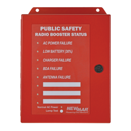
Annunciator Panel
Model: AP-8000B
Section
Safety Information........................................... 1
1.0. Circuit Board Illustration........................... 2
2.0. General Information................................. 3
3.0. Installation and Wiring............................. 4
4.0. Programming and RS-485 Features......... 6
6
.0.
7.0. Battery Back-up Option (6 Volt DC).......... 8
8.0. Specifications............................................ 8
9.0. Regulatory Information............................ 9
10.0. Troubleshooting...................................... 9
11.0. Limited Warranty.................................... 9
12.0. AP-8000B Power Source Options............ 10
Wiring Diagram............................................... 11
PoweringTheNetwork.com
Page
7
Phone: 714-751-0488
E-Mail: techservice@newmarpower.com
M-AP8000B
As of 110320
Fax: 714-896-9679
Advertisement
Table of Contents

Related Manuals for NewMar PE Series


Summary of Contents for NewMar PE Series
-
Page 1: Table Of Contents
PE Series Annunciator Panel Installation/Operation Manual Model: AP-8000B Section Page Safety Information........... 1 1.0. Circuit Board Illustration......2 2.0. General Information......... 3 3.0. Installation and Wiring......4 4.0. Programming and RS-485 Features..6 5.0. Summary Alarm Option (Auto Dialer)..7 RS-485 &... -
Page 2: Safety Information
Safety Information FOR COMMERCIAL USE ONLY CAUTION Up to 60 Volts DC may be present on the terminals. DO NOT SHORT ACROSS THE POWER SUPPLY TERMINALS • Keep fingers and all metal objects from power terminals and wires. • Use insulated hand tools. •... -
Page 3: Circuit Board Illustration
1.0 Circuit Board Illustration Func�on DIP Switch Factory Default Posi�ons: Form C Pos 1 & 2: On Alarm Pos 3 & 4: Off Outputs Sect. 3.4 to FACP Alarm LEDs (8), (8), Sect. 3.7 Sect. 3.7 EXPANSION Micro-processor PORT Func�on Indicator, Sect. -
Page 4: General Information
2.0 General Information Features: 2.1. The AP-8000B is a Microprocessor controlled fire alarm annunciator panel for use with In-building 2-Way Emergency Radio Communication Enhancement Systems (ERCES) required by the National Fire Protection Agency (NFPA 1221). It monitors the alarms of the Bi-Directional Amplifier (BDA) and Battery Back-up Unit (BBU) and provides visual and audible alarms as well as communicates these alarms to the fire control panel viaup to eight sets of form C alarm contacts. -
Page 5: Installation And Wiring
The Annunciator provides one “Form-C” relay output for up to (8) eight alarm conditions to the building’s main fire alarm panel control panel (FACP) or other device. Typical UL-2524 installations require at least the following alarm conditions to be annunciated: 1. - Page 6 Note: Wiring diagrams for EOL resistor wiring for Non-UL PE (BBU) follows. See Section 12 on page 10 for wiring diagrams for EOL resistor wiring for Newmar UL PE (BBU). Figure 4A: End of Line Resisitor Installation Non-UL Newmar PE (BBU) Resistor Installa�on for Monitoring Normally Open Contacts Note: BDS alarm contacts state shown on front panel are shown GND/ Return with no power or ba�ery connected to the BDS-DIN UPS.
-
Page 7: Programming And Rs-485 Features
Figure 4B: End of Line Resisitor Installation Non-UL Newmar PE (BBU) Resistor Installa�on for Monitoring Normally Closed Contacts Note: BDS alarm contacts state shown on front panel are shown GND/ Return with no power or ba�ery connected to the BDS-DIN UPS. As... -
Page 8: Summary Alarm Option (Auto Dialer)
4.2 Address Switch (see Figure 5): 4-Position DIP switch (right side of processor): Figure 5: Address DIP Switch This sets the annunciator address in binary. (0 - 15). Set a unique address for each annunciator panel. Example: Address Remote #1: ON/ON/OFF/OFF Remote #2: ON/ON/ON/OFF Switches Remote #3: ON/ON/ON/ON... -
Page 9: Battery Back-Up Option (6 Volt Dc)
Figure 7: Battery Back-up 7.1 Materials Required: 1 x 6 volt, 1.2 AH sealed valve regulated lead acid battery with F2 terminals (.187”). Newmar p/n 591-0126-0. 1 x Two position ckt. board mating connector -provided Power Failure 2 x .187” Female Fast-on crimp lugs- provided Alarm 2 x 18 to 22 AWG insulated wires, red &... -
Page 10: Regulatory Information
11.0 Limited Warranty Newmar warrants that the AP-8000B PE Series Annunciator Panel to be free from defects in material and workmanship for two years from date of purchase. If a problem with your AP-8000B or if you have any questions about the installation and proper operation of the unit, please contact NEWMAR’s Technical Services Department:... -
Page 11: Ap-8000B Power Source Options
12.0 AP-8000B Power Source Options Figure 8: Newmar UL Series PE Power Output (All DC Models) BBU DC Output Install 2A Fuse To BDA Input To AP-8000B Input Power Figure 9: Newmar Non-UL Series PE Power Output BDS-DIN-UPS 12-10 BDS-DIN-UPS 24-10... -
Page 12: Wiring Diagram
Annunciator Panel to Newmar UL PE Series BBU Wiring Diagram: 48V Example AC Disconnect Circuit Breaker Battery Disconnect Circuit Breaker AP‐8000B Alarm Inputs: 48VDC BDS‐DIN‐UPS AP‐8000B Annunciator Panel Model Shown 1. AC Fail 2. Low Battery/ Disconnect 3. Charger Fail EXPANSION To Front Door Status LED’s PORT POWER FAILURE 4. BDA Fail LED 9 LOW BATTERY RESET 5. Antenna Fail CHARGER FAILURE 5 6 7 8 9 10 6.Active RF Device Fail SILENCE BATTERY 1 2 3 4 5 6 7 8...
Need help?
Do you have a question about the PE Series and is the answer not in the manual?
Questions and answers