Table of Contents
Advertisement
Quick Links
Advertisement
Table of Contents

Related Manuals for Abs Company Glute Coaster ABS1011

Summary of Contents for Abs Company Glute Coaster ABS1011
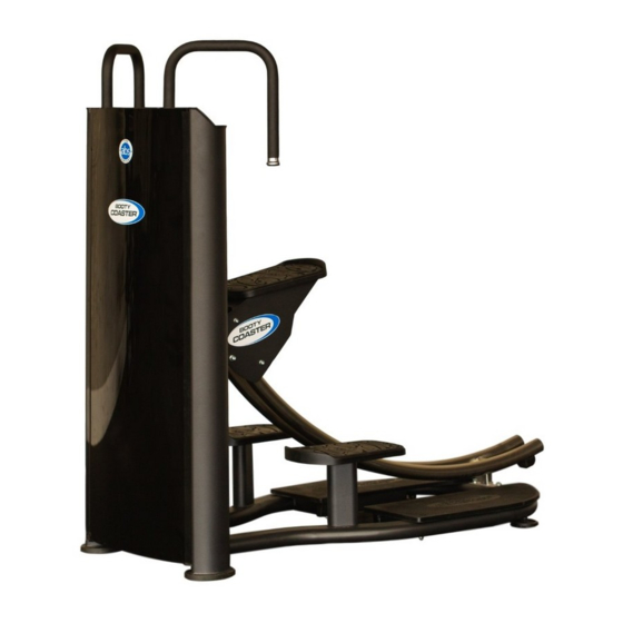
- Page 1 Owners Manual Model #ABS1011 ® Warranty information inside...
-
Page 2: Table Of Contents
TABLE OF CONTENTS Important Safety Instructions....pg. 3 Instructions..........pg. 4 Parts List............pg. 5 Exploded View..........pg. 6 Measurement Guide........pg. 7 Assembly Instructions.......pg. 8 Assembly............pg. 9 General Maintenance Schedule....pg. 17 General Maintenance Information...pg. 18 Training Tips..........pg. 19 Warranty............pg. 20 CAUTION Read all precautions and instructions in the manual before using this equipment. -
Page 3: Important Safety Instructions
IMPORTANT SAFETY INSTRUCTIONS Before beginning any fitness program, you should obtain a complete physical examination from your physician. When using exercise equipment, basic precautions should always be taken, including the following: 1. Read all instructions before using the equipment. These instructions are written to ensure your safety and to protect the unit. -
Page 4: Instructions
INSTRUCTIONS I N S T R U C T I O N S Before beginning assembly please take the time to read instructions thoroughly. Please use Before beginning assembly, please take the time to read instructions thoroughly. the various lists in this manual to make sure that all parts have been included in your Please use the various lists in this manual to make sure that all parts have been shipment.When ordering, use part number and description from the lists. -
Page 5: Parts List
PARTS LIST Item No. Qty Item No. Description Description Main Frame Small Roller PVC Foot Pad 169*129*16 Left Base Frame Rear Rubber Pad Right Base Frame Front Connection Frame Rail Bumper Weight Plate Bumper Rear Base Frame Flat Bumper Rail Frame Φ114 Pulley Carriage Left Handle ASSY... -
Page 6: Exploded View
EXPLODED VIEW... -
Page 7: Measurement Guide
MEASUREMENT GUIDE Bolt Bolt Bolt Bolt... -
Page 8: Assembly Instructions
Assembly Instructions------------------------------------------------------------------------------------------ 8 ASSEMBLY INSTRUCTIONS Assembly----------------------------------------------------------------------------------------------------------- 9 Maintenance Schedule--------------------------------------------------------------------------------------- 12 Assembly of the equipment takes professional installers about 1.5 hours. If this is the first time you have assembled this type of equipment, plan to General Maintenance Information------------------------------------------------------------------------- 13 spend more time. If you are in doubt about any part of this assembly, we recommend you contact a professional installer to complete the assembly. -
Page 9: Assembly
ASSEMBLY STEP 1 1. Fit the Left Base Frame (#2), the Right Base Frame (#3), and the Rear Base Frame (#5) to- gether as in the picture by inserting these parts into each other. 2. Assemble Left Platform Pad (#10) and Right Platform Pad (#11) on the base frame using: twelve Φ10.6*Φ26*2 Large Washers (#55) ten M10 Nuts (#57) Note: Be sure to use two Large Washers (#55) between the Left and Right Pedal ASSY (#10) - Page 10 ASSEMBLY STEP 2 1. Attach the Base Frame ASSY (#2) to the Main Frame (#1) using: two Fixing Plates (#31) four M10*130 Socket Head Cap Bolts (#60) eight Φ11*Φ20*2 Flat Washers (#52) four M10 Nuts (#57) 2. Adjust the two rear Feet (#28) to ensure the machine sits on the floor stably. 3.
- Page 11 ASSEMBLY STEP 3 1. Loosely attach the Front Connection Frame (#4) to the Main Frame ASSY (#1) using: four Φ11*Φ20*2 Flat Washers (#52) four Φ10 Spring Washers (#54) four M10*25 Socket Head Cap Bolts (#63) 2. Loosely attach the Back Support Frame (#73) to the Main Frame ASSY (#1) using: two Φ11*Φ20*2 Flat Washers (#52) two Φ10 Spring Washers (#54) two M10*25 Socket Head Cap Bolts (#63)
- Page 12 ASSEMBLY STEP 4 1. Insert the Upper Front Shroud (#21) at the top of the Main Frame (#1) by sliding it into the two grooves on either side of the frame. Slide the Upper Front Shroud (#21) all the way down until the top of the shroud is flush with top of the groves on the Main Frame (#1), then feed the cable through the access hole at the top of the shroud.
- Page 13 ASSEMBLY STEP 5 1. Unscrew both Cross Pan-Headed Screws (#72) to loosen both Guide Rod Bushings (#32). Remove the Guide Rod Bushings (#32) and set aside. 2. Install the 17 10lb Weight Plates (#36), then install Added Weight Plate Cover (#35). 3.
- Page 14 ASSEMBLY STEP 6 1. Placing cable over pulley (#45), slip the Pulley into the Φ114 Pulley Frame (#12) and secure using: two Φ11*Φ20*2 Flat Washers (#52) one M10 Nut (#57) one M10*45 Socket Head Cap Bolt (#65) 2. Attach the Φ114 Pulley Frame (#12) to the Main Frame (#1) using: four Φ11*Φ20*2 Flat Washers (#52) two M10 Nuts (#57) two M10*45 Socket Head Cap Bolts (#65)
- Page 15 ASSEMBLY STEP 7 1. Attach the Left Handle ASSY (#8) and the Right Handle ASSY (#9) to the Main Frame (#1) using: eight Φ11*Φ20*2 Flat Washers (#52) four M10 Nuts (#57) four M10*80 Socket Head Cap Bolts (#61) 2. Install Back Shroud (#22) into groves on either side of back of Main Frame (#1). Please be sure that both sides are in the groves and then slide the Back Shroud all the way down until it is flush with the top of the Main Frame.
- Page 16 ASSEMBLY STEP 8 1. Install the Carriage (#7) on Rail Frame (#6) from rear of machine. 2. Attach the 2 Rail Bumpers (#42) to the Rail Frame (#6) using: (Please note the direction of rubber bumper.) two Φ9*Φ16*1.6 Flat Washers (#51) two M8*25 Socket Head Cap Bolts (#67) 3.
-
Page 17: General Maintenance Schedule
GENERAL MAINTENANCE SCHEDULE A fitness facility should have a regular maintenance schedule in place that this equipment can be added into. For personal, in home use, please follow the home maintenance schedule listed above. -
Page 18: General Maintenance Information
GENERAL MAINTENANCE INFORMATION Links, Pull-Pins, Snap Hooks, Swivels, Weight Stack Pins: • Check all pieces for signs of visible wear or damage. • Check springs in snap hooks and pull-pins for proper tension and alignment. • If the spring sticks or has lost its rigidity, replace it immediately. Upholstery: •... -
Page 19: Training Tips
TRAINING TIPS Use this manual to guide you through the basic exercises you can perform on your equipment. To gain maximum results and avoid possible injury, consult a fitness professional to develop your complete exercise program. Always consult your physician before starting any exercise program. To be successful in your exercise program, it is important to develop an understanding of the basic principles of strength training. -
Page 20: Warranty
Manufacturer’s Limited Warranty The manufacturer warrants that your Glute Coaster™ is free of defect in materials and workmanship and will, at its option, repair or replace any defective Glute Coaster™ that is returned to it. Except as described in the following sentence, all parts and components of the Glute Coaster™ are warrantied from the original date of purchase as below: Frame - 3 years Cables - 6 months... - Page 21 Proof of Purchase will be required for all warranty claims. Our phone number is: (866) 219-5335 x0 (outside the U.S. 1-908-879-2713 x0) www.theabscompany.com The Abs Company, P.O. Box9 Chester, NJ 07930 info@theabscompany.com 1-866-219-5335 - www.TheAbsCompany.com © 2018 The Abs Company. All Rights Reserved.
Need help?
Do you have a question about the Glute Coaster ABS1011 and is the answer not in the manual?
Questions and answers