Table of Contents
Advertisement
Quick Links
Advertisement
Table of Contents

Related Manuals for lifeSMART HW93233SMQR


Summary of Contents for lifeSMART HW93233SMQR
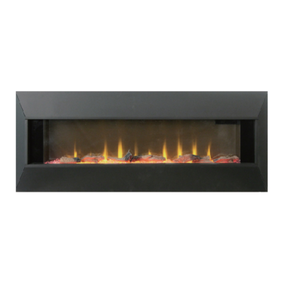
- Page 1 Owner’s Manual WALL MOUNT FIREPLACE HW93233SMQR IMPORTANT SAFETY INFORMATION: Always read this manual first before attempting to install or use this stove. For your safety, always comply with all warnings and safety instructions contained in this manual to prevent personal...
-
Page 2: Table Of Contents
Table of Contents Installation Options ........... 7 Important Instructions..........3 Wall Hanging ............8 Warranty ..............4 ........Fuel Bed Setup Instructions Pre-Assembly ............. 5 ........ Metal Frame Setup Instructions Hardware Included ........... 5 Operation ..............15 Product S ..........5 Care &... -
Page 3: Important Instructions
Important Instructions When using electrical appliances,basic Do not use outdoors. ⑤ precautions should always be followed ⑥ To disconnect heater, turn controls to off, and to reduce the risk of fire, electric shock, then remove plug from outlet. and injury to persons, including the Do not insert or allow foreign objects to enter ⑦... -
Page 4: Warranty
Warranty... -
Page 5: Pre-Assembly
Pre-Assembly HARDWARE INCLUDED Part Description Part Number Quantity Anchor Screw 180000010600 Wall Anchor 300000190100 180000010100 Screw 4mm x 8mm XXXXXXXXXX Inner hexagonal bolt M4mmx10mm XXXXXXXXXX Outer hexagonal nut M4mm XXXXXXXXXX Inner hexagonal bolt Tool NOTE: Hardware not shown to actual size. PRODUCT SPECIFICATIONS Voltage 120 VAC, 60 Hz... -
Page 6: Package Contents
Pre-Assembly (continued) PACKAGE CONTENTS NOTE: The scale and size of parts may be different depending on your exact model. Part Description Quantity Mounting Bracket-bottom Mounting Bracket-top Fireplace Front Glass Horizontal Trim Longitudinal Trim Remote Control AAA Battery Varies Logs Media Crystal Media Varies Screw Set... -
Page 7: Wall Hanging
Installation - Wall Hanging Operation Hanging on a wall Your new electric fireplace may be installed virtually somewhere in your home. However, when choosing a location be sure to follow the general instructions included. For best results install out of direct sunlight. Power supply service must be either completed or placed within the electric fireplace prior to finishing to avoid reconstruction. - Page 8 Installation - Wall Mounting Operation Choosing a Wall Location Drilling the Holes Choose a wall location to attach the Mounting Bracket (B). Drill five 7/25 in. (7 mm) holes in the wall. Insert the Wall Anchors (BB) into the holes using Position the Mounting Bracket (B) in the desired location.
- Page 9 Installation - Wall Mounting (continued) Operation Operation Hanging the Fireplace Hang the Fireplace (C&D) on the hook at the top of the Top Mounting Bracket (B) and let the Fireplace (C&D) sit onto the Bottom Mounting Bracket (A). C&D...
- Page 10 Installation - Wall Mounting (continued) Operation Operation Securing the Fireplace Secure the fireplace (C&D) to the Bottom Mounting Bracket (A) with the retaining Screw (CC). Continue to the fuel bed setup instructions (Page 15).
-
Page 11: Fuel Bed Setup Instructions
Fuel Bed Setup Instructions Operation Removing the Frame Remove the four screws that attach the Frame (D) to the Fireplace (C) and remove the Frame (D). Placing the Logs and media pieces Place the Crystal Media Pieces (J) on the Fuel bed. Place the Logs Media(I) on the Crystal Media Pieces (if need a Log effect view). - Page 12 Metal Frame Setup Instructions Operation The Wall Fire provided 2 Frames options, it can be Frame option either front glass or Metal Frame, the Metal Frame is covering the front glass when it was fixed. Jointing and Securing the Trims Take one Horizontal Trim (E) and one Longitudinal Trim (F), joint and align the 3 holes on the edges.
-
Page 13: Metal Frame Setup Instructions
Metal Frame Setup Instructions (Continued) Operation Removing the fitting screws on Fireplace Remove 4 screws on the fireplace (2screws on top and 2 on the bottom). Hooking the Metal Frame Put and hook top flange onto the fireplace top. Push and hook the Frame bottom. - Page 14 Metal Frame Setup Instructions (Continued) Operation Securing the screws onto the Fireplace Secure Removed 4 screws back on the fireplace (2screws on top and 2 on the bottom).
- Page 15 Operation Operation Display Control Panel 4. Thermostat up button 1. Power Button 4. Thermostat Down button 3. Heater Button 2. Flame effect button 4. Thermostat Down button 3. Heater Button 4. Thermostat up button 7. Color themes button 5. Brightness button 7.
-
Page 16: Operation
Operation (continued) Operation Adjusting the Flame Effect Powering the Fireplace Push the Power button to supply power to all functions Turns the Flame Effect On and Off, actived by pressing the of the fireplace and put the wall fire in a standby mode. button on the remote. - Page 17 Operation (continued) Operation Adjusting the Color Themes Using the Power Cord Correctly Pr ess the Themes button on the control panel or remote control to change the Color Themes. There are 8 settings: OFF, Red, This heater is for use on 120 volts. The cord has a plug Sky Blue,Orange, Blue, Purple, Green and Cycling as indicated as shown in the figure.
-
Page 18: Care & Cleaning
Care and Cleaning Clean the metal trim using a soft cloth, slightly dampened with a citrus oil-based product and buff with a soft, clean cloth. DO NOT use brass polish or household cleaners as these products will damage the metal trim. Purchase citrus oil-based products at a hardware store. -
Page 19: Troubleshooting
Troubleshooting PROBLEM POSSIBLE CAUSE CORRECTIVE ACTION front Display shows “ ”. The thermostat sensor is broken that the thermostat is plugged into the main circuit board. If this does not or disconnected. solve the problem contact customer service for a replacement thermostat sensor. -
Page 20: Replacement Parts
For replacement parts, call our customer service department at 1-800-986-3460, 8 a.m.-7 p.m., EST, Monday-Friday, 9 a.m. - 6 p.m., EST, Saturday. Part Description Part Number Qty. HW93233SMQR-A Remote Control - 8 Buttons 1set Screw Set HW93233SMQR-B 1set Logs Media...
Need help?
Do you have a question about the HW93233SMQR and is the answer not in the manual?
Questions and answers