Advertisement
Quick Links
T echnical
Manual
Table of Contents
Specification......................................1
Parts List ...........................................2~6
Adjustment........................................7~8
Case Outline ....................................9~10
PCB Assembly ..................................11~12
Wiring Diagram .................................13
Schematic Diagram ..........................14~16
Specifications
FM Tuner
Usable Sensitivity:
14.2 dBf
50dB Quieting Sensitivity:
20.2 dBf (mono)
45.3 dBf (stereo)
Signal to Noise Ratio (at 65 dBf):
73 dBf (mono)
70 dBf (stereo)
Harmonic Distortion (at 65dBf):
0.2% (mono)
0.3% (stereo)
Frequency Response:
10 Hz-15 kHz, ±3 dB
Capture Ratio:
2.0 dB
Alternate Channel Selectivity:
47 dB (±400 kHz)
Spurious Response Ratio:
90 dB
Image Rejection Ratio:
80 dB
IF Rejection Ratio:
80 dB
AM Suppression Ratio:
55 dB
Stereo Separation
(100Hz/1 kHz/10 kHz):
40 dB/45 dB/35 dB
Output level:
1V
Antenna Input:
75 ohms unbalanced
SHINSEN-BLD. 4F 10-10 SHINSEN-CHO, SHIBUYA-KU,
TOKYO 150-0045, JAPAN
Quality Uncompromised
AM Tuner
Usable Sensitivity:
500 µV/m
Selectivity:
25 dB
Harmonic Distortion:
0.5%
Image Rejection Ratio:
45 dB
Signal to Noise Ratio:
40 dB
Output level:
500 mV
Antenna Input:
Loop Antenna
General
Power Consumption:
10 watts
Power Requirements (AC):
115 volts, 60 Hz (USA version)
230 volts, 50 Hz (European version)
Dimensions (W x H x D):
435 x 73 x 319 mm
17
" x 2
" x 10
"
1/8
7/8
9/16
Panel Height
60 mm / 2
3
/
8
"
Weight:
3.9 Kg/8.6 lb.
®
AM/FM STEREO TUNER
RT-02
Serial. NO.
Beginning
Y-360A-0207/pdf
Advertisement

Related Manuals for Rotel RT-02


Summary of Contents for Rotel RT-02
-
Page 1: Table Of Contents
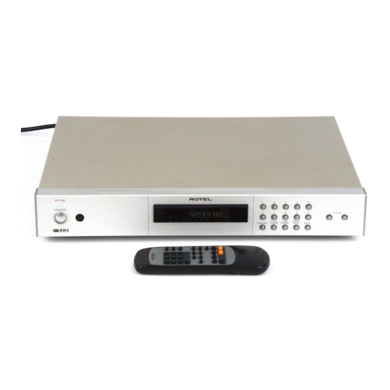
Quality Uncompromised ® T echnical AM/FM STEREO TUNER RT-02 Manual Table of Contents Specification........1 Parts List ...........2~6 Adjustment........7~8 Case Outline ........9~10 PCB Assembly ........11~12 Wiring Diagram .........13 Schematic Diagram ......14~16 Specifications FM Tuner AM Tuner Usable Sensitivity: Usable Sensitivity: 14.2 dBf 500 µV/m... - Page 2 Appearance RT-02 RBDS TP TA AF STEREO TUNED AUTO MEMORY PRESET...
-
Page 3: Parts List 1/4
RT-02 Parts List 1/4 SYMBOL PARTS NO. DESCRIPTION 016 X-1320A01-04 PCB ASSY 501X-1320-B PCB ASSY JK301 066 4TR-2166#4 2P PIN JACK AU (WHT. RED) JK302 065 YKB21-5103A 3.5Φ MINI JACK JK303 065 YKB21-5111A 3.5Φ MINI JACK R301,315 053 CR14-101J-A CARBON RESISTOR 1/4W 100... - Page 4 Parts List 2/4 SYMBOL PARTS NO. DESCRIPTION D202 034 TRD6.2JST1 ZENER DIODE 6.2V (AB2) 016 E-1319A00 PCB ASSY 501E-1319-B PCB ASSY C116,117 047 ECJ2VF1H473Z CERAMIC CAPACITOR CHIP 50V0.047uF C110-112 047 ECJ2VF1H104Z CERAMIC CAPACITOR CHIP 50V0.1uF C115 047 ECJ2VG1H102J CERAMIC CAPACITOR CHIP 50V1000pF C101-105,114 047 ECJ2VG1H101J CERAMIC CAPACITOR CHIP 50V100pF...
- Page 5 Parts List 3/4 SYMBOL PARTS NO. DESCRIPTION IC04 031 BU1920F IC (RDS) 021 2648601430 MICRO INDUCTOR 20.8mH 042 TP50V332J MYLAR CAPACITOR 0.0033uF C30,48 042 TP50V223J MYLAR CAPACITOR 0.022uF 042 TP50V393J MYLAR CAPACITOR 0.039uF RL57,RR57 055 ERJ6GEYJ152V RESISTOR CHIP 1.5K 055 ERJ6GEYJ182V RESISTOR CHIP 1.8K R16,34,39 055 ERJ6GEYJ101V...
- Page 6 Parts List 4/4 SYMBOL PARTS NO. DESCRIPTION 012 UC3-03A01 TACT BUTTON 15KEY(BLACK) 012 UC3-03A00 TACT BUTTON 15KEY(SILVER) 012 UC3-04A01 TACT BUTTON 2KEY(BLACK) 012 UC3-04A00 TACT BUTTON 2KEY(SILVER) 014 C-4550A03 UPPER COVER(BLACK) 014 C-4550A24 UPPER COVER(SILVER) 082 OMRT-02-1 OWNER'S MANUAL(EFGIDSSw) 072 4TR-3228 FM DIPOLE ANT...
- Page 7 4. Confirm if 'STEREO' & 'TUNED' turns OFF when decreasing the output level slowly from 26dB to 25dB, 24dB ~~~. (Repeat the above 3. if not OFF in lower than 24dB.) 5. Push RT-02's TUNE UP or DOWN button "long" at Signal Generator Output Level 26dB and start Auto search. Confirm if search stops at FM Frequency 98.1MHz.
- Page 8 3. Confirm if 'TUNED' turns OFF when decreasing the output level of AM Signal Generator slowly from 84dB to 80dB. 4. Push RT-02 TUNE UP or DOWN button "long" at AM Signal Generator Output Level 84dB and start AUTO search.
-
Page 9: Case Outline
Case Outlines RT-02 OPA2604P KRC107M KRA107M KTC3198 DTC323TS AT24C16P PC817B TC74HCU04AP NJM317F LA1266 LA3401 BU1920F LM7001M CXP82832-316Q... - Page 10 Front PCB 016 E-1319A00 Bottom Side RT-02 PCB Assembly - 1 Front PCB 016 E-1319A00 Bottom Side Main PCB 016 X-1320A01-04 Top Side Main PCB 016 X-1320A01-04 Top Side...
-
Page 11: Pcb Assembly
PCB Assembly - 2 RT-02 Tuner PCB 4002002300 Top Side View Tuner PCB 4002002300 Bottom View... -
Page 12: Wiring Diagram
Wiring Diagram RT-02... -
Page 13: Schematic Diagram
RT-02 Schematic Diagram - 1 CXP82832-316Q CXP82832-347Q CXP82832-347Q OPTION of OTP IC... - Page 14 Schematic Diagram - 2 022 T-1065N01 OPA2604AP 5.1K OPA2604AP POWER...
- Page 15 Schematic Diagram - 3...
Need help?
Do you have a question about the RT-02 and is the answer not in the manual?
Questions and answers