Table of Contents

Subscribe to Our Youtube Channel
Related Manuals for Ridder LogicDrive RLD200


Summary of Contents for Ridder LogicDrive RLD200
- Page 1 Product Manual Ridder LogicDrive RLD200 265110EN - 2017.07 - V03 Ridder Drive Systems Lorentzstraat 36-38 3846 AX Harderwijk P.O. Box 360 3840 AJ Harderwijk The Netherlands T +31 (0)341 416 854 F +31 (0)341 416 611 I www.ridder.com E info@ridder.com...
-
Page 2: Table Of Contents
LogicDrive RLD200 technical specifications ........ -
Page 3: Logicdrive Rld200 Description
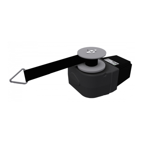
The standard RLD200 is finished with a graphite grey powder coating. 2.2 LogicDrive RLD200 application The LogicDrive RLD200 drive units are designed to adjust the positions of air inlet flaps, air valves and ventilation curtains in livestock houses and crop storage buildings. -
Page 4: Logicdrive Rld200 Technical Specifications
2.3 Technical specifications LogicDrive RLD200 Mechanical Torque 200 Nm Speed 1 rpm Winch belt speed 15-22 cm/min Winch belt length 1 m | 2 m Rotational range between end positions 0,25-100 rev Drive unit Self-locking Dimensions (WxHxD) 110 mm x 150 mm x 230 mm... -
Page 5: Logicdrive Rld200 Winch Belt Pull Force For Ventilation Systems
2.5 LogicDrive RLD200 winch belt pull force for ventilation systems Winch belt forces depend on: ● Type of LogicDrive RLD200 (one-or two-sided output drive shaft, single or double winch strap). ● The required winding length of the winch belt. Winding length limitations: ●... -
Page 6: Logicdrive Rld200 Packaging Contents
2.6 LogicDrive RLD200 packaging contents Each LogicDrive RLD200 unit is packaged in a box together with its accessories. The following table shows which items are supplied in each box. 3.1 LogicDrive RLD200 mounting positions Please observe the following mounting positions when installing the LogicDrive RLD200. -
Page 7: Mounting The Logicdrive Rld200
3.2 Mounting the LogicDrive RLD200 Mount the LogicDrive RLD200 according to the following instructions and in a mounting position as described in §3.1. Please ensure that the RLD200 is mounted securely, so that the building structure can sufficiently absorb the forces applied. -
Page 8: Mounting The Belt Drum And Winch Belt
3.3 Mounting the belt drum and winch belt Mount the belt drum and winch belt (or belts) for the RLD200 as follows: Ridder Drive Systems T +31 (0)341 416 854 F +31 (0)341 416 611 I www.ridder.com... -
Page 9: Pre-Winding The Winch Belt Onto The Belt Drum
3.4 Pre-winding the winch belt onto the belt drum To safely use the belt drum and winch belt of the LogicDrive RLD200, it is necessary to first pre-wind the belt onto the drum: Belt drum with a single belt: ● At least ¼ revolution. -
Page 10: Connection And Operation - Abbreviations
Note: If longer cable lengths are required, you can consider compensating for the voltage loss by increasing the supply voltage of the LogicDrive RLD200. A conductor diameter of 1.5 mm² requires a 1 V DC increase per 10m of cable length and a diameter of 2.5 mm² requires a 1 V DC increase per 15 m of cable length (both in addition to the relevant value specified in the table). -
Page 11: Logicdrive Rld200 Wiring Diagram And Operating Elements
4.3 LogicDrive RLD200 wiring diagram and operating elements The diagram below shows how to wire the LogicDrive RLD200. It also shows where the operating elements are located on the control board X1 and the motor board X2. Always use separate cables for the 24 V DC supply voltage and 0-10 V DC control signal. -
Page 12: Logicdrive Rld200 Rotational Direction, And End And Emergency Positions
4.4 LogicDrive RLD200 rotational direction, and the end and emergency positions The figure below shows the control buttons DIR A and DIR B along with the corresponding rotational direction of A and B. The figure also shows where the end and emergency positions are located relative to each other. -
Page 13: Conditions And Criteria For Teaching In The Logicdrive Rld200
A or B. 5.2 Operating the LogicDrive RLD200 Chapter 6 describes how to teach in the LogicDrive RLD200. This section describes the control op- tions for teaching in the RLD200. The DIP switch on the control board X1 allows Teach-in you to activate the teach-in mode of the RLD200. - Page 14 When operating the LogicDrive RLD200, do not exceed the limit positions to avoid damage or injury! To operate the unit in rotational direction A in Hold to run teach-in mode, press and hold down push button Operation ‘DIR A’. If end position A has been programmed, DIR A the RLD200 will stop at this position.
-
Page 15: Logicdrive Rld200 Status Leds
The table below provides an overview of common control signals of climate controllers. Please note that you must also correctly set up the control unit used (such as the Ridder LogicControl RLC101). To do so, see the manual of the control unit. -
Page 16: Teaching In The Logicdrive Rld200 - Programming The End Positions
6.1 Teaching in the LogicDrive RLD200 - Programming the end positions The following conditions apply to programming the end positions: ● No end position/positions may have been programmed (to erase end positions, see §6.3). ● The RLD200 must be taught in with the control signal of the climate controller! ●... - Page 17 ‘LED B’ starts blinking slower (③). Set the DIP switch S1 to ‘Operating mode’. End positions A and B have now been programmed. Ridder Drive Systems T +31 (0)341 416 854 F +31 (0)341 416 611 I www.ridder.com...
-
Page 18: Teaching In The Logicdrive Rld200 - Programming An Emergency Position
6.2 Teaching in the LogicDrive RLD200 - Programming an emergency position The following conditions apply to programming an emergency position: ● End positions A and B must have been programmed (see §6.1). ● The minimum value of the control signal must be greater than 1 V DC. -
Page 19: Teaching In The Logicdrive Rld200 - Erasing An End Position
6.3 Teaching in the LogicDrive RLD200 - Erasing an end position The following conditions apply to erasing an end position: ● The end position to be erased (A or B) must have been programmed (see §6.1). If an emergency position has been programmed,... -
Page 20: Teaching In The Logicdrive Rld200 - Erasing The Emergency Position
6.4 Teaching in the LogicDrive RLD200 - Erasing an emergency position The following conditions apply to erasing an emergency position: ● Emergency position C must have been programmed (see §6.2). Description Picture Set the DIP switch S1 to ‘Teach-in mode’. -
Page 21: Logicdrive Rld200 Alarm Contact
7.1 LogicDrive RLD200 alarm contact The LogicDrive RLD200 is equipped with an alarm contact, allowing the RLD200 to relay an alarm condition. The alarm contact is able to switch a 24 V AC/DC current of up to 1 A. While in ‘operating mode’ the alarm contact will switch under the following conditions: ●... - Page 22 A has not yet been programmed. ● Teach-in mode: End position A (the RLD200 is in this end position) has been programmed; end position B has not yet been programmed. Ridder Drive Systems T +31 (0)341 416 854 F +31 (0)341 416 611...
- Page 23 ● Teach-in mode: RLD200 is in the pre-programmed emergency position. ● Teach-in mode: The emergency position of the RLD200 has been erased. Ridder Drive Systems T +31 (0)341 416 854 F +31 (0)341 416 611 I www.ridder.com...
-
Page 24: Logicdrive Rld200 Maintenance
9.1 LogicDrive RLD200 maintenance Although the LogicDrive RLD200 is essentially maintenance free, it is recommended to regularly check the following while using the RLD200: ● The mechanical condition of the unit (e.g. wear and tear, winch belt or cable and fasteners). -
Page 25: Technical Support
For Technical Support please contact your local After Sales contact person. You will find your local After Sales contact person via our website www.ridder.com. 10.3 Environment End of life products from Ridder Drive Systems must be disposed according to local laws and/ or regulations. Ridder Drive Systems... -
Page 26: Logicdrive Rld200 Accessories
Ridder LogicControl RLC101 control unit for 1 LogicDrive RLD200. 587200 RLP200-24V DC Ridder LogicPower RLP200 emergency power supply for 1 LogicDrive RLD200 (requires LogicControl unit). 507220 MOUNTING SET RLD200 Mounting plate with fastening bolts for the RLD200. 590023 CHAIN COUPLING 1/2\z16\S\B1 Chain coupling (weld mounting) for 1”... -
Page 27: Meaning Of Warnings In This Product Manual
May result in minor injury if the hazard is not avoided. May result in significant injury, possible death, if the hazard is not avoided. Ridder Drive Systems T +31 (0)341 416 854 F +31 (0)341 416 611 I www.ridder.com... - Page 28 www.ridder.com...
Need help?
Do you have a question about the LogicDrive RLD200 and is the answer not in the manual?
Questions and answers