Advertisement
Advertisement
Table of Contents

Related Manuals for Full Boar BANDSAW


Summary of Contents for Full Boar BANDSAW
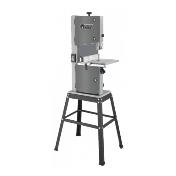
- Page 1 BANDSAW • 245mm • 420W POWER • 2 SPEED • HEAVY DUTY STAND INSTRUCTION MANUAL WARNING: Read all safety warnings and all instructions. Failure to follow the warnings and instructions may result in electric shock, fire and/or serious injury. Save all warnings and instructions for future reference.
-
Page 2: Specifications
SPECIFIC TIONS – MODEL NO. FBT-2450 Power: 420W Input: 220-240V ~ 50Hz No Load Speed: 1400/min Throat Depth: 245mm Blade Length: 1790mm Blade Width: 6-13mm Max Cutting Height: 120mm Blade Speed: 660 / 960 m/min Table Size: 300x330mm Weight (tool only): 33kgs KNOW YOUR PRODUCT... - Page 3 KNOW YOUR PRODUCT 1. Blade Tension Knob 13. Blade Tracking Knob 25. Long Side Support x 2 2. Upper Wheel 14. Motor 26. Leg x 4 3. Upper Blade Guide Knob 15. Stand 27. Rubber Feet x 4 4. Upper Blade Guide 16.
-
Page 4: Table Of Contents
T BLE OF CONTENTS SPECIFICATIONS………………………………………… Page 2 KNOW YOUR PRODUCT………………………………. Page 2 INTRODUCTION………………………………………... Page 5 SAFETY INSTRUCTIONS……………………………….. Page 5 ASSEMBLY……………………………………………….. Page 10 OPERATION …………………………………………….. Page 13 MAINTENANCE …………….………………………….. Page 19 CONTENTS ……………………………………………... Page 21 WARRANTY……………………………………………… Page 22... -
Page 5: Introduction
The electric motor has been designed for 230V and 240V only. Always check that the power supply corresponds to the voltage on the rating plate. Note: The supply of 230V and 240V on Full Boar tools are interchangeable for Australia and New Zealand. - Page 6 GENER L S FETY INSTRUCTIONS W RNING! Read all instructions. Failure to follow all instructions listed below may result in electric shock, fire and/or serious injury. The term “Power Tool” in all of the warnings listed below refers to your mains operated (corded) power tool or battery operated (cordless) power tool.
- Page 7 GENER L S FETY INSTRUCTIONS (cont.) d. Remove any adjusting key or wrench before turning the power tool on. A wrench or a key left attached to a rotating part of the power tool may result in personal injury. e. Do not overreach. Keep proper footing and balance at all times. This enables better control of the power tool in unexpected situations.
- Page 8 DDITION L S FETY RULES FOR B NDS WS Hold power tool by insulated gripping surfaces, when performing an operation where the cutting accessory may contact hidden wiring or its own cord. Cutting accessory contacting a “live” wire may make exposed metal parts of the power tool “live“...
- Page 9 DDITION L S FETY RULES FOR B NDS WS (cont.) W RNING! Some dust created by sanding, sawing, grinding, drilling and other construction activities contain chemicals known to cause cancer, birth defects or other reproductive harm. Some examples of these chemicals are: •...
-
Page 10: Assembly
SSEMBLY Unpacking: • Open carton and remove top packing material. • Carefully lift the Bandsaw from the packaging and place it on a level work surface. • Unpack the contents. ssembly of stand (15): Fig.1 The legs are constructed by assembling each half of the structure and then joining them together. - Page 11 (33) can be used to tension the bolts. The rubber feet (27) can now be Fig.10 attached to complete the stand. (Fig 10). 11. Place the bandsaw on the stand. Bolt (29), Nut & Washer (30) can be inserted and tightened (Fig 11). Fig.11...
- Page 12 (7). Note: The grate is a safety feature and should never be Fig.12 removed from the bandsaw. ssembling of saw table (19): 1. Remove plastic wing nut on underside of the saw table (19) (Fig 13).
-
Page 13: Operation
OPER TION Before adjusting the tension & tracking of the blade, please ensure the upper & lower guides are well clear of the blade (following the steps below). Upper guide • Loosen the guide block nut (Fig.18) to allow the entire upper blade guide (4) to move relative to the blade (5). - Page 14 OPER TION (cont.) djusting the blade tracking C UTION! The blade must be properly clamped before the blade can be adjusted. 1. Undo the turn-locks (9) and open the upper and lower doors (10) (Fig.22). Fig.22 2. Manually turn the upper wheel (2) slowly in a clockwise direction (Fig.23).
- Page 15 OPER TION (cont.) djusting the Blade Guides Guide bearings must be adjusted before using the product for the first time and anytime the blade (5) is changed. 1. Upper guide & support bearings. • Loosen the guide block nut (Fig.25) to allow the entire upper blade guide (4) to move relative to the blade (5).
- Page 16 OPER TION (cont.) • Slide the entire guide block forward, allowing the front edge of the guide bearings to sit 0.5mm from the front of the blade teeth (Fig.32). Once positioned, tighten the guide nut to lock into place. • Loosen the guide bearing retainer nuts (Fig.33) with the supplied hex key (32)
- Page 17 OPER TION (cont.) On/Off Switch (11) 1. To turn the bandsaw on, press the green button ON (I) (Fig.38). 2. To turn the bandsaw off, press the red button OFF (O). Note: In the event of a voltage failure an undervoltage relay will trip.
- Page 18 (31). Always keep the push stick (31) close at hand at the hook provided (12). Blade Selection Blade supplied with the bandsaw is designed for general purpose use. • Use a narrow blade to cut tighter radii than you can with a wider blade.
-
Page 19: Maintenance
(31). M INTEN NCE W RNING! To prevent serious injury from accidental operation: Turn the Power Switch of the bandsaw to its “OFF” position and unplug the bandsaw from its electrical outlet before performing any inspection, maintenance, or cleaning procedures. - Page 20 DESCRIPTION OF SYMBOLS Volts Hertz Alternating current Watts /min Revolutions or No load speed reciprocation per minute Warning Regulator compliance mark Wear eye, breathing, Read instruction manual ear protection C RING FOR THE ENVIRONMENT Power tools that are no longer usable should not be disposed of with household waste but in an environmentally friendly way.
-
Page 21: Contents
CONTENTS 1 x FBT-2450 Bandsaw 1 x Bag Bolts, Nuts & Washers 1 x Stand 2 x Hex Keys 1 x Rip Fence 2 x Spanners 10mm & 12mm 1 x Blade 1 x Slotted Screwdriver 1 x Mitre Fence... -
Page 22: Warranty
WARRANTY YOUR WARRANTY FORM SHOULD BE RETAINED BY YOU AT ALL TIMES. IN ORDER TO MAKE A CLAIM UNDER THIS WARRANTY YOU MUST RETURN THE PRODUCT TO YOUR NEAREST BUNNINGS WAREHOUSE (see www.bunnings.com.au or www.bunnings.co.nz for store locations) WITH YOUR BUNNINGS REGISTER RECEIPT. PRIOR TO RETURNING YOUR PRODUCT FOR WARRANTY PLEASE TELEPHONE OUR CUSTOMER SERVICE HELPLINE: Australia 1800 069 486 New Zealand 0508 069 486...
Need help?
Do you have a question about the BANDSAW and is the answer not in the manual?
Questions and answers
where is the starter capicitor on my FBT2450 bandsaw.