
Related Manuals for Turf Equipment Z-AERATE


Summary of Contents for Turf Equipment Z-AERATE
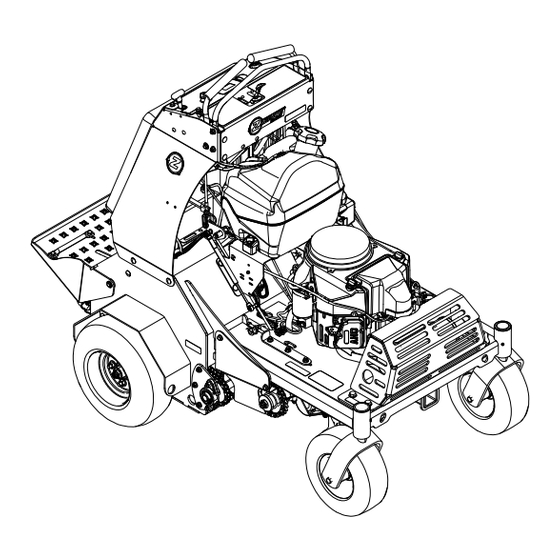
- Page 1 Z-AERATE ™ 30 INCH MODEL For Serial Nos. 408,644,346 & Higher Part No. 4505-292 Rev. A...
- Page 2 As configured to meet safety, emission, and operating requirements, the actual engine horsepower (or torque) on this class of machine will be significantly lower. ©2020 Z Turf Equipment is part of the Contact us at www.zturfequipment.com. Exmark® family of products Printed in the USA...
-
Page 3: Introduction
Introduction CONGRATULATIONS on the purchase of your Z-Aerate. This product has been carefully designed and manufactured to give you a maximum amount of dependability and years of trouble-free operation. This manual contains operating, maintenance, adjustment, and safety instructions for your Z-Aerate. -
Page 4: Table Of Contents
Contents Check Wheel Lug Nuts Torque Specification..........33 Check Spark Arrester (if equipped)....33 Introduction ............3 Thread Locking Adhesives......34 Safety ..............5 Adjustments ............35 Safety Alert Symbol ......... 5 Auxiliary Pump Drive Belt Adjustment ...35 General Safety ..........5 Transmission Drive Belt Tension ....35 Safety and Instructional Decals ....... -
Page 5: Safety
Safety Safety General Safety This machine is capable of amputating hands and Safety Alert Symbol feet and of throwing objects. Always follow all safety instructions to avoid serious personal injury. This Safety Alert Symbol (Figure 2) is used both in •... -
Page 6: Safety And Instructional Decals
• Keep all safety signs legible. Remove all grease, • New safety signs may be obtained from dirt and debris from safety signs and instructional your authorized Z Turf Equipment dealer or labels. distributor. • Replace all worn, damaged, or missing safety •... - Page 7 Safety decal121-6162 121–6162 1. Cutting/dismemberment hazard of hand or foot, tines—lower the tines to the ground; read the Operator’s Manual for disassembly procedure. g211619 Hour Meter/Tine Engagement Display 1. Parking brake 4. Depth setting lock 2. Tine ground engagement 5. See Operator’s manual foot switch lockout for operating conditions code...
- Page 8 Safety decal116-9392 116-9392 1. Read and understand the operator’s manual before 9. Check auxiliary hydraulic tank (Only use AW-32 hydro oil) servicing this machine. every 50 hours 2. Grease front caster pivots (2x) every 100 hours 10. Grease wheel bearings (2x) every 25 hours 3.
- Page 9 Safety decal121-6164 121-6164 1. Fast 6. Wheels and tines rotate when 11. Warning—keep bystanders away. moving backward 2. Slow 7. Continuous variable setting 12. Warning—do not operate the machine unless you are trained. 3. Neutral 8. Choke—on 13. Thrown object hazard—pick up debris before operating the machine.
-
Page 10: Specifications
Specifications Specifications Operator Controls • Steering and Motion Control Systems – Separate levers, on each side of the console, control speed and direction of travel of the respective drive wheels. Engine – Steering is controlled by varying the position • Engine Specifications: See your Engine Owner’s of the levers relative to each other. -
Page 11: Dimensions
Specifications Tires and Wheels Torque Requirements Drive Bolt Location Torque Front Caster Engine Mounting Bolts 17-23 ft-lb (23-31 N-m) Pneumatic Semi-Pneumatic (Air-Filled) Wheel Lug Nuts 85-105 ft-lb (115-142 N-m) Quantity Wheel Hub Nuts 211-260 ft-lb Tread Super Turf Smooth (286-352 N-m) Size 16 x 6.50-8 13 x 5.00-6... -
Page 12: Product Overview
Operation Product Overview Operation Note: Determine the left and right sides of the machine from the normal operating position. Controls Become familiar with all the controls before starting the engine and operating the machine. Motion Control Levers The motion control levers, located on each side of the top console, control the forward and reverse motion of the machine. - Page 13 Operation To release, push the handle forward into the detent. When parking on a steep slope, the wheels must be chocked or blocked in addition to the brake being engaged. The unit must be tied down and brake engaged when transporting. Ignition Switch Located on the right side of the control console.
- Page 14 Operation There are two ways to activate the display. Tap the multi-function switch either up or down to display the tine engagement meter. Step on the tine ground engagement foot switch. A higher number on the status bar increases the length of the aeration plug and a lower number decreases it.
- Page 15 Operation during transport to and from the jobsite, and when parked inside a building. Align valve handle with the fuel line to open. Rotate 90° to close. Drive Wheel Release Valves WARNING Hands may become entangled in the rotating drive components below the engine deck, which could result in serious injury or death.
-
Page 16: Before Operation
Not operate the machine unless they are in proper Figure 5). working condition. Replace worn or deteriorated parts with genuine Z Turf Equipment parts when This feature takes into account the weight of the necessary. operator so that the correct aerating pressure and plug... -
Page 17: Operating Instructions
Operation Fuel Safety the tank allows gasoline to expand. Overfilling may result in fuel leakage or damage to the engine DANGER or emission system. • Gasoline is harmful or fatal if swallowed. Gasoline is extremely flammable and vapors are Long-term exposure to vapors may cause serious explosive. - Page 18 Operation • Do Not operate the machine while ill, tired, or activity. Never assume that children will remain under the influence of alcohol or drugs. where you last saw them. • Operate the machine only in good visibility and – Keep children out of the working area and appropriate weather conditions.
- Page 19 Operation Starting the Engine Leave the motion control levers in neutral and engage the parking brake. Set the throttle to the “FAST” position. On a cold engine, pull the choke knob upward into the “ON” position. On a warm engine, leave the choke in the “OFF”...
- Page 20 Operation Adjusting the Tine Depth Setting the foot rocker bar hardware, slide the bar forward or rearward, and retighten hardware. Tap the multi-function switch up or down to set the aeration depth. Tap the bottom of the multi-function Locking/Unlocking the Tine Depth switch to increase the tine depth to remove a longer Setting plug.
- Page 21 Operation Driving the Machine CAUTION Machine can spin very rapidly by positioning one lever too much ahead of the other. Operator may lose control of the machine, which may cause damage to the machine or injury. • Use caution when making turns. •...
-
Page 22: After Operation
Operation g016673 Figure 13 g267535 To turn left or right, release pressure on the Figure 14 motion control lever toward the desired turn 1. Nut 2. Front reference/speed direction. control bar To make zero turns, lift your foot off of the tine ground engagement foot switch to raise the tines. -
Page 23: Transporting
Operation Transporting Loading a Machine Use extreme caution when loading machines on Transporting the Machine trailers or trucks. One full width ramp that is wide enough to extend beyond the rear tires is Use a heavy-duty trailer or truck to transport the recommended instead of individual ramps for each machine. -
Page 24: Maintenance
Use adequate jack stands. to the original equipment or failure to use • Carefully release pressure from components with original Z Turf Equipment parts could lead stored energy to serious injury or death. Unauthorized changes to the machine, engine, fuel or •... -
Page 25: Recommended Maintenance Schedule(S)
Maintenance Recommended Maintenance Schedule(s) Maintenance Service Maintenance Procedure Interval • Change the engine oil. • Check the transmission output shaft nut torque specification. After the first 5 hours • Check the wheel hub nuts torque specification. • Change the auxiliary hydraulic reservoir filter and fluid. After the first 100 hours •... -
Page 26: Engine Safety
Maintenance Engine Safety DANGER Charging or jump starting the battery may WARNING produce explosive gases. Battery gases can The engine can become very hot, especially the explode causing serious injury. muffler and exhaust components. Touching a • Keep sparks, flames, or cigarettes away from hot engine can cause severe burns. - Page 27 Maintenance short lengths to reduce voltage drop between Voltage Percent Maximum Charging systems. Make sure the cables are color coded or Reading Charge Charger Interval labeled for the correct polarity. Settings 12.6 or 100% 16 volts/7 CAUTION Charging greater amps Required Connecting the jumper cables incorrectly 12.4 –...
-
Page 28: Check Tines
Maintenance g012785 Figure 16 1. Positive (+) cable on discharged battery 2. Positive (+) cable on booster battery 3. Negative (–) cable on the booster battery 4. Negative (–) cable on the engine block 5. Booster battery 6. Discharged battery 7. -
Page 29: Check The Safety Interlock
Maintenance Check the Safety Interlock Important: It is essential that the operator safety mechanisms be connected and in proper operating condition prior to use. Note: If machine does not pass any of these tests, Do Not operate. Contact an Authorized Service Dealer. Check the Normal Engine Starting Circuit System Parking Brake... -
Page 30: Check For Loose Hardware
Maintenance Check for Loose Hardware remove the filter by unscrewing it. Make sure no oil drains onto the belt drives through the holes in Service Interval: Before each use or daily the engine deck. Before the new filter is installed, apply a thin coating of Exmark 4–Cycle Premium Stop engine, wait for all moving parts to stop, and Engine Oil on the surface of the rubber seal. -
Page 31: Check Tire Pressures
Maintenance Stop engine and wait for all moving parts to stop, Stop engine, wait for all moving parts to stop, and and remove key. Engage parking brake. remove key. Engage parking brake. With the unit cold, check the expansion tank and Inspect sprockets for wear and replace as required. -
Page 32: Check Spark Plug
Maintenance Change Auxiliary Hydraulic Lubrication Chart (cont'd.) Reservoir Fluid and Filter Service Interval: After the first 100 hours Fitting Initial Number of Service Locations Pumps Places Interval Every 250 hours thereafter 7. Belt Idler Yearly Stop engine, wait for all moving parts to stop, and Pivot remove key or spark plug wire(s). -
Page 33: Check Transmission Output Shaft Nut Torque Specification
Maintenance Check Transmission Unscrew filters to remove and allow oil to finish draining from drive system. Output Shaft Nut Torque Important: Before reinstalling new filters, Specification apply a thin coat of Exmark Premium Hydro Oil on the surface of the filters rubber seal. Service Interval: After the first 5 hours Turn the filters clockwise until rubber seal Yearly thereafter... -
Page 34: Thread Locking Adhesives
Maintenance Thread Locking Adhesives Wait for muffler to cool. If any breaks in the screen or welds are observed, Thread locking adhesives such as “Loctite 242” replace arrester. or “Fel-Pro, Pro-Lock Nut Type” are used on the following fasteners: If plugging of the screen is observed, remove arrester and shake loose particles out of the Sheave retaining bolt in end of engine crankshaft. -
Page 35: Adjustments
Maintenance Adjustments Note: Shut off engine, wait for all moving parts to stop, engage parking brake, and remove key before servicing, cleaning, or making any adjustments to the unit. Auxiliary Pump Drive Belt Adjustment Stop engine, wait for all moving parts to stop, and remove key. -
Page 36: Adjusting The Parking Brake
Maintenance Adjusting the Brake Switch To adjust, loosen the idler bolt and push down on the sprocket to tension the chain. Park the machine on a level surface. Recheck the chain tension and tighten the idler Shut off engine and wait for all moving parts to bolt. -
Page 37: Caster Pivot Bearings Pre-Load Adjustment
Maintenance Caster Pivot Bearings Push the control levers all the way forward to the front reference bar. Pre-Load Adjustment • If the control levers contact the reference Remove dust cap from caster and tighten nyloc nut bar, allow the control levers to return to until washers are flat and back off 1/4 of a turn neutral. -
Page 38: Cleaning
Maintenance Cleaning Remove cooling shrouds from engine and clean cooling fins. Also clean dust, dirt, and oil from external surfaces of engine which can cause Cleaning and Storing Safety improper cooling. • Park machine on level ground, disengage drives, Make sure cooling shrouds are properly reinstalled. set parking brake, stop engine, and remove key. - Page 39 Maintenance Federal law states that batteries should not be placed in the garbage. Management and disposal practices must be within relevant federal, state, or local laws. If a battery is being replaced or if the unit containing the battery is no longer operating and is being scrapped, take the battery to a local certified recycling center.
-
Page 40: Troubleshooting
Troubleshooting Troubleshooting Important: It is essential that all operator safety mechanisms be connected and in proper operating condition prior to use. When a problem occurs, do not overlook the simple causes. For example: starting problems could be caused by an empty fuel tank. The following table lists some of the common causes of trouble. - Page 41 Troubleshooting Problem Possible Cause Corrective Action Engine overheats. 1. Engine load is excessive. 1. Reduce the ground speed or aeration depth. 2. Oil level in the crankcase is low. 2. Add oil to the crankcase. 3. Cooling fins and air passages for the 3.
-
Page 42: Schematics
Schematics Schematics Electrical Schematic g269827... - Page 43 Schematics Hydraulic Diagram g270316...
-
Page 44: Information
California Proposition 65 Warning Information What is this warning? You may see a product for sale that has a warning label like the following: WARNING: Cancer and Reproductive Harm—www.p65Warnings.ca.gov. What is Prop 65? Prop 65 applies to any company operating in California, selling products in California, or manufacturing products that may be sold in or brought into California. It mandates that the Governor of California maintain and publish a list of chemicals known to cause cancer, birth defects, and/or other reproductive harm. - Page 45 Notes:...
- Page 46 Service Record Date: Description of Work Done: Service Done By:...
- Page 48 Model No. Engine Serial No. (E/No) Serial No. ©2020 Z Turf Equipment is part of the Exmark® family of products All Rights Reserved Printed in the USA 415 Industrial Row • Beatrice, NE 68310 • (402) 223-6375 • Fax (402) 223-5489 www.zturfequipment.com...
Need help?
Do you have a question about the Z-AERATE and is the answer not in the manual?
Questions and answers