Table of Contents
Advertisement
Quick Links
Advertisement
Table of Contents

Related Manuals for Turf Equipment Z-AERATE

Summary of Contents for Turf Equipment Z-AERATE
- Page 1 Z-AERATE ™ For Serial Nos. 406,294,345 & Higher Part No. 4504-916 Rev. A...
- Page 2 (or torque) on this class of machine will be y lower. ©2020 Z Turf Equipment is part of the Contact us at www.zturfequipment.com. Exmark® family of products Printed in the USA 415 Industrial Row...
-
Page 3: Introduction
All Z-Aerate parts are thoroughly tested and inspected before leaving the factory, however, attention is required on your part if you are to obtain the fullest measure of satisfaction and performance. -
Page 4: Table Of Contents
Contents Clean Engine and Exhaust System Area ............41 Remove Engine Shrouds and Clean Introduction ............3 Cooling Fins..........41 Safety ..............5 Clean Debris From Machine ......41 Safety Alert Symbol ......... 5 Waste Disposal ..........42 General Safety ..........5 Troubleshooting ............43 Safety and Instructional Decals ....... -
Page 5: Safety
General Safety This machine is capable of amputating hands and The intended use of this machine is for lawn care. feet and of throwing objects. Z Turf Equipment designed and tested this machine to offer reasonably Safety Alert Symbol safe service; however, failure to comply with safety instructions may result in injury or death. -
Page 6: Safety And Instructional Decals
• Keep all safety signs legible. Remove all grease, • New safety signs may be obtained from dirt and debris from safety signs and instructional your authorized Z Turf Equipment dealer or labels. distributor. • Replace all worn, damaged, or missing safety •... - Page 7 Safety decal142-3908 142-3908 1. Read the instructions before servicing or performing 6. Check tire and caster wheel pressure (4 locations) maintenance 2. Time interval 7. Grease cylinder lift; refer to the Operator's manual for further instructions (2 locations) 3. Check engine oil level 8.
- Page 8 Safety 142-4373 Spreader / Sprayer Calibration: Mixing of liquid or dry product should be in accordance to manufacturers labels. Remember this is designed for low volume spraying so the mix will be more concentrated. CAPACITY _______SPACING ________ Remember that your machine is factory set to put down 1/3 gallon of liquid per 1,000 sq. ft ( at 5MPH and CAPACITY 20"...
- Page 9 Safety decal142-4317 142-4317 1. Fast 15. Spreader speed 2. Slow 16. Spreader speed—Increase 3. Neutral 17. Spreader speed—Decrease 4. Reverse 18. Spray pump—On; optional sprayer accessory 5. Warning-Read the Operator’s Manual. Do Not operate this 19. Spray pump—Off; optional sprayer accessory machine unless you are trained.
-
Page 10: Specifications
Specifications Specifications – Steering is controlled by varying the position of the levers relative to each other. • Parking Brake Handle: Engages the parking brake. Systems • Tine Adjustment Control: Raises and lowers the tines. Engine • Engine Specifications: See your Engine Owner’s Transmission Manual •... -
Page 11: Torque Requirements
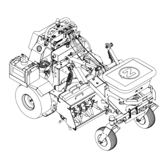
Product Overview Overall Height: Product Overview 49.5 inches (125.7 cm) Tread Width: (Outside to Outside of Tires, Widthwise) 46 inches (116.8 cm) Curb Weight: 1460 lb (662 kg) Torque Requirements Bolt Location Torque Engine Mounting Bolts 121-144 in-lb (13.3-15.8 N-m) g315886 Figure 3 Wheel Lug Nuts... -
Page 12: Operation
Operation Operation Note: Determine the left and right sides of the machine from the normal operating position. Controls Become familiar with all the controls before starting the engine and operating the machine. Motion Control Levers The motion control levers, located on each side of the top console, control the forward and reverse motion of the machine. - Page 13 Operation When parking on a steep slope, the wheels must be Use the deflector control to temporarily stop or chocked or blocked in addition to the brake being deflect granules away from sidewalks, parking lots, engaged. The machine must be tied down and brake patios, or anywhere granules are not desired to be engaged when transporting.
- Page 14 Operation g310379 Figure 8 g027033 Figure 7 1. LH drive wheel release 3. Tighten drive wheel valve release valve 1. Slot–maximum position 2. Linkage 2. Loosen drive wheel 4. RH drive wheel release release valve valve With the Spreader On/Off handle in the “OFF” Release the parking brake.
-
Page 15: Before Operation
• Evaluate the terrain to determine what accessories and attachments are needed to properly and safely perform the job. Only use accessories and attachments approved by Z Turf Equipment. • Inspect the area where the equipment is to be used and remove all rocks, toys, sticks, wires, bones, and other foreign objects. -
Page 16: Pre-Start
Operation Chemical Safety • Have clean water available. • Do Not eat, drink, or smoke while working with WARNING chemicals. Chemical substances used in the spreader system • Always wash your hands and other exposed areas may be hazardous and toxic to you, bystanders, as soon as possible after finishing the work. - Page 17 Operation DANGER DANGER In certain conditions gasoline is extremely In certain conditions during fueling, static flammable and vapors are explosive. electricity can be released causing a spark which can ignite gasoline vapors. A fire or explosion A fire or explosion from gasoline can burn you, from gasoline can burn you and others and cause others, and cause property damage.
-
Page 18: Operating Instructions
Operation flame or any enclosed area where open pilot lights • The owner/user can prevent and is responsible or heat appliances are present. for accidents or injuries occurring to himself or herself, other people or property. Operating Instructions • This machine was designed for one operator only. Do not carry passengers and keep all others away from machine during operation. - Page 19 Operation • Tragic accidents can occur if the operator is not WARNING alert to the presence of children. Children are Hands, feet, hair, clothing, or accessories can often attracted to the machine and the working become entangled in rotating parts. Contact activity.
- Page 20 Operation injury or death. The operator is responsible for • Avoid starting, stopping or turning the machine safe slope operation. Operating the machine on on slopes. Avoid making sudden changes in speed any slope requires extra caution. Before using the or direction;...
- Page 21 Operation Lowering the Tines Driving the Machine DANGER CAUTION The rotating tines are dangerous. Tine contact Machine can spin very rapidly by positioning one can cause serious injury or death. lever too much ahead of the other. Operator may lose control of the machine, which may cause Do Not put hands or feet under the machine damage to the machine or injury.
- Page 22 Operation g317334 Figure 13 To turn left or right, release pressure on the motion control lever toward the desired turn g317231 Figure 12 direction. To make zero turns, raise the tines using the right thumb switch. To turn left or right, pull the motion control lever back toward neutral in the desired turn direction.
-
Page 23: Operating The Spreader
Operation Use the Spreading Chart on the following pages to determine the rate dial and linkage. Note: If the setting is not listed for the type of material being used, place the setting at a lower value then adjust as needed. Drive to the work area. - Page 24 Operation Evaluate the spread pattern. If adjustments are needed see the Spreader Calibration/Pattern Adjustment section. When finished spreading, close the hopper gate. Clean the hopper after each spreading session. Important: Always empty and clean the spreader immediately after each use. Failure to do so may cause the chemicals to corrode the spreader and other components.
-
Page 25: Spreader Calibration
Operation Place the rate dial and linkage to a setting lower than the maximum open position. Allow the spreader to completely dry before the next use. Lightly oil spreader components to help reduce corrosion. Spreader Calibration The spreader should be calibrated each time a new material is used. - Page 26 Operation Note: This measurement is the effective Reference the Spreading Charts section to determine the appropriate rate dial setting (see spreading width. Figure 7). Calculating the Application Rate Fill the hopper approximately half-full with the desired material. Determine the amount of product to be applied. Set the impeller speed to the appropriate Determine the calibration course broadcasting rate.
- Page 27 Operation For this example, 5 lb (2.3 kg) was applied to 1,000 ft (93 m If necessary, adjust the rate dial to achieve the recommended amount to be applied and repeat the procedure. Once the correct application rate is achieved, repeat this procedure an additional time to verify the results.
- Page 28 Operation Spreading Charts Note: The Dial Settings chart and the Grass Seed Spreading chart are provided with permission from the Brinly-Hardy Company; reference the Brinly-Hardy Company website for more information. These charts are to be used as an approximate guideline only. Other factors, such as weather conditions, spreader operation, and condition of materials, will affect the results.
- Page 29 Operation The chart below is for reference only. When spraying and spreading at the same time, set the spread pattern to twice the width of the spray; this will help avoid striping and streaking. For example, standard spray width = 9 ft (2.7 m) and spread width = 18 ft (5.4 m).
- Page 30 Operation Removing the Aerator Head The aerator head is removable for service, cleaning and removing from traction unit to install other attachments. To remove the aerator head from the traction unit: Adjust the hydraulic cylinder so that the aerator head starts to make contact with the ground (taking weight off of the head).
-
Page 31: After Operation
Operation After Operation General Safety • Park machine on level ground, disengage drives, set parking brake, stop engine, remove key or disconnect spark plug wire. Wait for all movement to stop and allow the machine to cool before adjusting, cleaning, repairing, or storing. Never allow untrained personnel to service machine. - Page 32 Operation truck. Steeper angles may also cause the machine to tip backward. If loading on or near a slope, position the trailer or truck so it is on the down side of the slope and the ramps extends up the slope. This will minimize the ramp angle.
-
Page 33: Maintenance
While maintenance or adjustments are being to the original equipment or failure to use made, someone could start the engine. original Z Turf Equipment parts could lead Accidental starting of the engine could seriously to serious injury or death. Unauthorized injure you or other bystanders. -
Page 34: Recommended Maintenance Schedule(S)
Maintenance • Keep hands and feet away from moving parts. CAUTION If possible, Do Not make adjustments with the Raising the machine for service or engine running. If the maintenance or adjustment maintenance relying solely on mechanical procedure require the engine to be running and or hydraulic jacks could be dangerous. -
Page 35: Periodic Maintenance
Maintenance Periodic Maintenance DANGER Charging or jump starting the battery may produce explosive gases. Battery gases can Check Engine Oil Level explode causing serious injury. Service Interval: Before each use or daily • Keep sparks, flames, or cigarettes away from battery. - Page 36 Maintenance short lengths to reduce voltage drop between Voltage Percent Maximum Charging systems. Make sure the cables are color coded or Reading Charge Charger Interval labeled for the correct polarity. Settings 12.6 or 100% 16 volts/7 CAUTION Charging greater amps Required Connecting the jumper cables incorrectly 12.4 –...
-
Page 37: Check Tines
Maintenance Stop engine, wait for all moving parts to stop, and remove key. Engage parking brake. Visually inspect machine for any loose hardware or any other possible problem. Tighten hardware or correct the problem before operating. Service Air Cleaner Service Interval: Every 250 hours—Replace the primary air cleaner element —... -
Page 38: Check Hydraulic Oil And Reservoir Level
Maintenance Lubricate Grease Fittings the filter adapter, then tighten filter an additional 2/3 to 3/4 turn. Note: See chart for service intervals. Clean around oil fill cap and remove cap. Fill to specified capacity and replace cap. Stop engine, wait for all moving parts to stop, and remove key. -
Page 39: Change Hydraulic Filters And Fluid
Maintenance Change Fuel Filter Hydro Oil Service Interval Exmark Premium Hydro After first 250 hours Service Interval: As required *Every 500 hours thereafter A fuel filter is installed in the fuel line between the fuel tank and the engine. Replace when necessary. Mobil 1 15W-50 After first 250 hours *Every 250 hours... -
Page 40: Check Spark Arrester (If Equipped)
Maintenance Adjustments Torque the wheel lug nuts to 90-95 ft-lb (122-129 N-m). Note: Shut off engine, wait for all moving parts to stop, engage parking brake, and remove key before Check Spark Arrester servicing, cleaning, or making any adjustments to (if equipped) the unit. -
Page 41: Cleaning
Maintenance Cleaning Clean Engine and Exhaust System Area Service Interval: Before each use or daily (May be required more often in dry or dirty conditions.) CAUTION Excessive debris around engine cooling air intake and exhaust system area can cause engine, exhaust area, and hydraulic system to overheat which can create a fire hazard. -
Page 42: Waste Disposal
Maintenance guards, around the fuel tank, around engine and exhaust area. Important: You can wash the machine with mild detergent and water. Do not pressure wash the machine. Avoid excessive use of water, especially near the control panel, around the engine, hydraulic pumps, and motors. -
Page 43: Troubleshooting
Troubleshooting Troubleshooting Important: It is essential that all operator safety mechanisms be connected and in proper operating condition prior to use. When a problem occurs, do not overlook the simple causes. For example: starting problems could be caused by an empty fuel tank. The following table lists some of the common causes of trouble. - Page 44 Troubleshooting Problem Possible Cause Corrective Action Machine pulls left or right (with levers fully 1. Tire pressure in drive tires not correct. 1. Adjust tire pressure in the drive tires. forward). 2. Tracking needs adjustment. 2. See Motion Control Linkage Adjustment in Adjustments section.
-
Page 45: Schematics
Schematics Schematics Electrical Schematic g317546... -
Page 46: Information
California Proposition 65 Warning Information What is this warning? You may see a product for sale that has a warning label like the following: WARNING: Cancer and Reproductive Harm—www.p65Warnings.ca.gov. What is Prop 65? Prop 65 applies to any company operating in California, selling products in California, or manufacturing products that may be sold in or brought into California. It mandates that the Governor of California maintain and publish a list of chemicals known to cause cancer, birth defects, and/or other reproductive harm. - Page 47 Service Record Date: Description of Work Done: Service Done By:...
- Page 48 Engine Serial No. (E/No) Serial No. Z Turf Equipment is part of the Exmark® family of products. © 2020 Exmark Mfg. Co., Inc. All Rights Reserved. Printed in the USA. 415 Industrial Row • Beatrice, NE 68310 • (402) 223-6375 • Fax (402) 223-5489...
Need help?
Do you have a question about the Z-AERATE and is the answer not in the manual?
Questions and answers