Table of Contents
Advertisement
Quick Links
Advertisement
Table of Contents

Related Manuals for Lutz-Jesco C 7700


Summary of Contents for Lutz-Jesco C 7700
- Page 1 Chlorine control valve C 7700 Operating instructions Read the operating manual! The user is responsible for installation and operation related mistakes! Dosing Original operating instructions BA-20710-02-V05 Liquids Conveying Gases © Lutz-Jesco GmbH 2017 Control Systems...
-
Page 3: Table Of Contents
2.5 Personal protective equipment ..........15 Spare parts ...............30 2.6 Personnel qualification ............. 15.1 Individual parts for C 7700 up to 2500 g/h ......3 Intended use ..............8 15.2 Individual parts for C 7700 from 4 kg/h ......... 3.1 Notes on product warranty ............ -
Page 4: Notes For The Reader
Chlorine control valve C 7700 Operating instructions 1 Notes for the Reader 1.3 Explanation of the warning signs This operating manual contains information and behaviour rules for the safe and designated operation of the device. Warning signs represent the type and source of a danger:... -
Page 5: Safety
Chlorine control valve C 7700 Operating instructions 2 Safety 2.1 General warnings WARNING The following warnings are intended to help you eliminate the dangers Increased risk of accidents due to insufficient qualifica- that can arise while handling the control valve. Risk prevention measures tion of personnel! always apply regardless of any specific action. -
Page 6: Hazards Due To Non-Compliance With The Safety Instructions
Chlorine control valve C 7700 Operating instructions 2.3 Hazards due to non-compliance with the safety Wear the following personal protective equipment when performing the instructions following tasks: Commissioning, Failure to follow the safety instructions may endanger not only persons, All work on gas-bearing sections of the plant, but also the environment and the device. - Page 7 Chlorine control valve C 7700 Operating instructions 2.6.4 Personnel tasks In the table below you can check what qualifications are the pre-condi- tion for the respective tasks. Only people with appropriate qualifications are allowed to perform these tasks! Qualification Activities...
-
Page 8: Intended Use
3.2 Intended purpose The regulation valve C 7700 is intended for the adjustment of the gas mass flow only. It may only be used in vacuum dosing systems. The device was designed for use with chlorine, which has a minimum chlorine mass content of 99.5 %. -
Page 9: Product Description
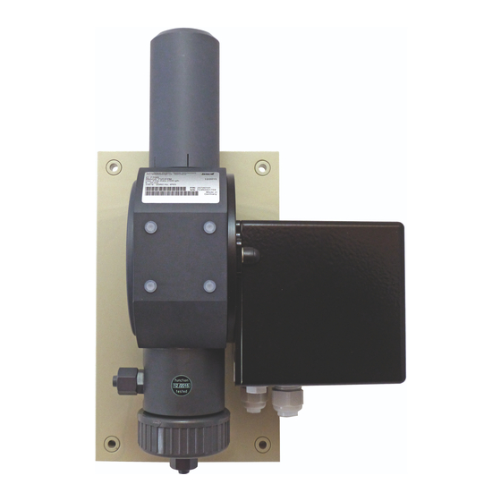
Valve with servomotor Wall panel and installation material (optional) Operating instructions The regulation valve C 7700 is often supplied as a module together with the flow meter. The flow meter is described in a separate document. 4.2 Design 4.2.1 Structure of the device Fig. -
Page 10: Rating Plate
Max. XXX l/h XXXX V 50/60 Hz, IP65 P/N: *102A12345678* S/N: XXXXXXXXXX Made in *12345678012345* Germany Fig. 3: Rating plate C 7700 Item Description Product name Components coming into contact with the media Max. dosing quantity Control signal Voltage supply... -
Page 11: Technical Data
Chlorine control valve C 7700 Operating instructions 5 Technical data Description Value 80, 200, 500, 1000, 2500 g Cl dosage range 4, 5, 10, 15, 25, 40, 60, 120, 200 kg Cl Operating pressure -1...0 bar Required suction vacuum of the injector -0.25 bar... -
Page 12: Dimensions
Chlorine control valve C 7700 Operating instructions 6 Dimensions All dimensions in millimetres (mm). Fig. 4: Dimensional drawing Connection (IN / OUT) Dim. L1 Dim. L2 Dim. L3 Hose 8/12 mm Hose 12/16 mm Threaded connection DN15 / Ø20 75.5 Screw connection DN32 / Ø40... -
Page 13: Installation
Chlorine control valve C 7700 Operating instructions 7 Installation 7.2 Installing the device WARNING Increased risk of accidents due to insufficient qualifica- CAUTION tion of personnel! Danger of personal injury and material damage! Chlorinators and their accessories must only be installed, operated and maintained by personnel with sufficient qualifications. -
Page 14: Hydraulic Installations
Chlorine control valve C 7700 Operating instructions 7.3 Hydraulic installations 7.3.2 Pipe length and nominal width 7.3.1 Back-pressure regulator For instance, PVC-U pipes or PE hoses are used as vacuum lines. The following nominal widths are recommended for the vacuum line The regulation valve requires a constant differential pressure in order to between dosing device and injector (max. - Page 15 Chlorine control valve C 7700 Operating instructions If the recommended nominal width for the pipe line is larger than the connection of the device, fit pipes with the same size as the connection straight onto the device and observe the recommended nominal width for the large distance.
-
Page 16: Completing The Installation
Chlorine control valve C 7700 Operating instructions 7.3.3 Establish the hose connection 7.3.4 Make the PVC seal connection. Precondition for action: Precondition for action: ü ü The device is fitted on the wall. The device is fitted on the wall. -
Page 17: Installation Plans
Chlorine control valve C 7700 Operating instructions 7.5 Installation plans 7.5.1 Proportional dosing without control circuit 7.5.2 Dosing with closed control circuit Fig. 9: Installation example 1 Fig. 10: Installation example 2 Item Description Item Description Flow meter Flow meter... -
Page 18: Servomotors
ð Replace damaged cables or components without delay. Regulation signal 3-point step The regulation valve C 7700 can be equipped with various servomotors. Position feedback 0 - 1000 Ohm This section describes the electrical connection for the various versions and how they are operated. - Page 19 Chlorine control valve C 7700 Operating instructions 8.2.3 Limit switch adjustment Item Description SL microswitch (valve closed) The servomotor in its delivery state is adjusted to a setting range of 0-100 %. A different setting is only useful in special SR microswitch (valve open) cases.
-
Page 20: Servomotor 4-20 Ma
Chlorine control valve C 7700 Operating instructions 8.3 Servomotor 4-20 mA Item Description 8.3.1 Technical data Status display LEDs Potentiometer hysteresis Description Value Signal connections 20 mA input and output Programming keys 230 V ±10 %, 50/60 Hz ±5 %, optional:... - Page 21 Chlorine control valve C 7700 Operating instructions 8.3.3 Operator controls of the servomotor Hysteresis potentiometer LEDs Direction Position rotation arrange- Meaning (colour) ment Clockwise Increase hysteresis Anti- 1 (blue) Operation Reduce hysteresis clockwise Fault Manual mode right-hand Voltage supply failure Hyster.
- Page 22 Chlorine control valve C 7700 Operating instructions 10. Switch DIP switch 2 to automatic operation. ü The servomotor is programmed. 8.3.5 Select signal type The servomotor can be used with these two signals: 0-20 mA 4-20 mA In the delivery state, it is adjusted to 4-20 mA. A line rupture is detected with this signal type, and the relay registers it as a "fault".
-
Page 23: Control
Chlorine control valve C 7700 Operating instructions 9 Control 10 Operation 10.1 Setting the dosing quantity No operation is required in the normal mode. The electrical regulation valve adjusts the dosing quantity automatically, depending on the control signal. If necessary, the device can be locked on the fully open position to allow manual operation (see section 9.1 „Manual operation“... -
Page 24: Start-Up
Chlorine control valve C 7700 Operating instructions 11 Start-up 4. Set the dosing quantity on the manual dosing valve. Observe the 11.1 Vacuum system leak test application process to prevent overdosing. Adapt the dosing quantity is necessary. 5. When the chlorine value corresponds approximately to the setpoint... -
Page 25: Short-Term Shutdown
Chlorine control valve C 7700 Operating instructions 12 Shutdown 12.1 Short-term shutdown 12.3 Disposal of old equipment Before disposing of the old equipment, you must clean off the Perform the following working steps: remaining chlorine by rinsing it with nitrogen or air. -
Page 26: Maintenance
Chlorine control valve C 7700 Operating instructions 13 Maintenance 13.2 Maintenance accessories Products by Lutz-Jesco are manufactured to the highest quality standards and have a long service life. However, some parts are subject to operational wear. This means that regular visual inspections are Description necessary to ensure a long operating life. - Page 27 Chlorine control valve C 7700 Operating instructions 13.4.3 Fitting the valve 5. Loosen the large bottom union nut on the valve and remove the valve seat by turning it gently. 6. If the valve has a throughput of 4000 g/h or more, unscrew the valve Perform the following working steps: disc from the valve disc holder.
- Page 28 Chlorine control valve C 7700 Operating instructions Adjusting the zero point Fig. 19: Zero point adjustment 5. Move the electrical regulation valve to the closed position. 6. Loosen the counternut on the upper guide bolt. 7. Turn the adjusting spindle on the ball knob until the flow meter indicates zero throughflow.
-
Page 29: Troubleshooting
Chlorine control valve C 7700 Operating instructions 14 Troubleshooting All possible errors are listed in this table. Problem Possible cause Remedy The system does not achieve its full The manual valve on the flow meter is not Open valve. dosing capacity. -
Page 30: 15 Spare Parts
Chlorine control valve C 7700 Operating instructions 15 Spare parts 15.1 Individual parts for C 7700 up to 2500 g/h Fig. 20: Individual parts for C 7700 up to 2500 g/h Spare parts BA-20710-02-V05 © Lutz-Jesco GmbH 2017 Individual parts for C 7700 up to 2500 g/h... - Page 31 Valve seat with hose connection U washer Ø5.3 Cap nut G2 Sealing bushing Table 28: Individual parts for C 7700 up to 2500 g/h Table 28: Individual parts for C 7700 up to 2500 g/h Spare parts © Lutz-Jesco GmbH 2017 BA-20710-02-V05 Subject to technical changes.
-
Page 32: Individual Parts For C 7700 From 4 Kg/H
40 kg/h to Screws for servomotor and eccentric 200 kg/h Table 30: Maintenance sets Fig. 21: Individual parts for C 7700 from 4 kg/h Position Description Position numbers that are not mentioned are identical with valves up to 2500 g/h... - Page 33 Chlorine control valve C 7700 Operating instructions 16 EU Declaration of Conformity (DE) EU-Konformitätserklärung Hiermit erklären wir, dass das nachfolgend bezeichnete Gerät aufgrund seiner Konzipierung und Bauart sowie in der von uns in Verkehr gebrachten Ausführung den einschlägigen grundlegenden Sicherheits- und Gesundheitsanforderungen der aufgeführten EG-Richtlinien entspricht. Bei einer nicht mit uns abgestimmten Änderung am Gerät verliert diese Erklärung ihre Gültigkeit.
- Page 34 Chlorine control valve C 7700 Operating instructions 17 Declaration of no objection Please copy the declaration, stick it to the outside of the packaging and return it with the device. Declaration of no objection Please fill out a separate form for each appliance! We forward the following device for repairs: Device and device type: ..............
- Page 35 Chlorine control valve C 7700 Operating instructions 18 Warranty claim Warranty claim Please copy and send it back with the unit! If the device breaks down within the period of warranty, please return it in a cleaned condition with the complete warranty claim.
- Page 36 Chlorine control valve C 7700 Operating instructions 19 Index Back-pressure regulator ..............14 Personal protective equipment ............6 Personnel qualification ...............6 Personnel tasks .................7 Product description ................9 Chlorine .....................5 Product warranty ................8 Corrosion ...................5 Rating plate ..................10 Declaration of no objection ..............34 Design ....................9...
Need help?
Do you have a question about the C 7700 and is the answer not in the manual?
Questions and answers