
Related Manuals for Brooks Automation PFC-552HC

Summary of Contents for Brooks Automation PFC-552HC
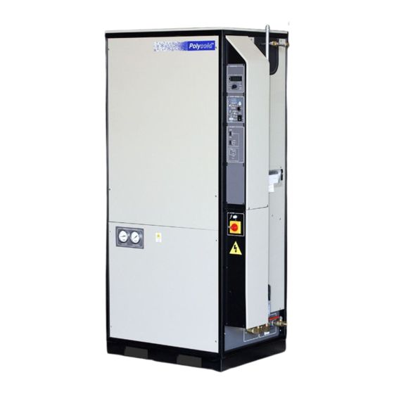
- Page 1 Polycold Fast Cycle (PFC) Water Vapor Cryopump Operation Manual 825160-00, revision B...
- Page 2 WAVE, WAVE II, Zaris, and Z-Bot are trademarks of Brooks Automation Hardware. All other trademarks are properties of their respective owners. © Brooks Automation 2011, All Rights Reserved. The information included in this manual is Brooks Proprietary Information and is provided for the use of Brooks customers only and cannot be used for distribution, reproduction, or sale without the expressed written permission of Brooks Automation.
-
Page 3: Table Of Contents
PFC Operation Manual 1. Introduction Contents Introduction ..........................3 Description and Applications ...................... 3 PFC Versions..........................6 PFC Performance Specifications....................7 Using this Manual ........................9 Safety ............................. 10 Overview ........................... 10 Safety Alerts Defined ........................ 11 Safety Precautions for the PFC ....................13 Safety Guidelines ........................ - Page 4 1. Introduction PFC Operation Manual This Page left Intentionally Blank 825160-00, revision B...
-
Page 5: Introduction
PFC Operation Manual 1. Introduction 1. Introduction Description and Applications WARNING Do not attempt to perform any installation, operation, or maintenance procedures on the PFC until you have thoroughly read and understood the information in the Safety section of this Manual. Failure to heed this warning can result in serious injury or death. - Page 6 1. Introduction PFC Operation Manual Description and Applications, Continued Figure 1. PFC Used to Capture Water Vapor Legend: A. Refrigeration Unit B. Refrigerant line C. Cryogenic feedthough D. Vacuum chamber wall E. Cryosurface Continued on next page 825160-00, revision B...
- Page 7 PFC Operation Manual 1. Introduction Description and Applications, Continued Figure 2. PFC Used to Minimize Backstreaming Legend: A. Refrigeration Unit B. Refrigerant line C. High vacuum valve D. Cryobaffle E. Oil diffusion pump 825160-00, revision B...
-
Page 8: Pfc Versions
1. Introduction PFC Operation Manual PFC Versions The PFC is manufactured in a number of different models and configurations to fit a variety of applications. Table 1 below shows the currently manufactured PFC models. Table 2 describes the nomenclature used in the PFC model numbering system. Table 1. -
Page 9: Pfc Performance Specifications
Table 3 compares the performance specifications of four models of the PFC. This table is intended to be representative of the PFC product family. For more information about specific PFC models, contact Brooks Automation Polycold Systems. Table 3. PFC Models Performance Specifications... - Page 10 1. Introduction PFC Operation Manual PFC Performance Specifications, Continued Table 4. PFC Models Performance Specifications, Continued Parameter 1101 LT 552 HC 672 HC 1102 HC Utilities Cooling water flow rate, l/min. (gal/min.) At 13 C (55 F) 11.6 (3.1) 4.9 (1.3) 6.8 (1.8) 13.6 (3.6) At 26 C (79 F)
-
Page 11: Using This Manual
PFC Operation Manual 1. Introduction Using this Manual This Operation Manual contains operation, safety, and specifications information for the PFC, While this document covers specific information and adjustments for the PFC, there is installation, maintenance, troubleshooting, and repair information in other manuals which can affect the settings or operating mode of the PFC and attached components. -
Page 12: Safety
The emergency and safety procedures are provided to help service personnel develop safe practices and establish safe conditions for working with the PFC. Brooks Automation assesses the safety of each product we manufacture. The safety issues generated during the PFC assessment are discussed in this manual. The complete Safety Analysis is available upon request. -
Page 13: Safety Alerts Defined
PFC Operation Manual 2. Safety Safety Alerts Defined Danger, Warning, and Caution alerts are integral parts of this manual and are also located on, and in, the PFC. Danger, Warning, and Caution alerts must be read carefully, understood thoroughly, and observed at all times. If this equipment is used in a manner not specified, the protection provided by the equipment may be impaired. - Page 14 2. Safety PFC Operation Manual Safety Alerts Defined, Continued Preview and understand the safety alerts used in this manual before operating or performing any work on the PFC. Safety warnings are provided in this manual before each step that may involve hazards to personnel.
-
Page 15: Safety Precautions For The Pfc
PFC Operation Manual 2. Safety Safety Precautions for the PFC General Safety Precautions The following safety alerts apply specifically to the PFC. Read and understand them before performing any adjustments or service on the PFC. WARNING GENERAL HAZARD Failure to review this manual could result in death or serious injury. Review this manual before performing any procedure including routine operation of Brooks Polycold PFC. - Page 16 2. Safety PFC Operation Manual Safety Precautions for the PFC, Continued General Safety Precautions, Continued DANGER GENERAL HAZARD Do not bypass or change the setting of any protective devices. Resetting of a protective device may void the warranty and, if not avoided, may cause death or serious injury.
- Page 17 PFC Operation Manual 2. Safety Safety Precautions for the PFC, Continued Specific Hazards and how to Avoid Them, Continued Refrigerant is harmful to the environment and to human health. Refrigerant in 1101 models may also be flammable. WARNING CHEMICAL HAZARD Do not release refrigerant to the atmosphere.
-
Page 18: Safety Guidelines
2. Safety PFC Operation Manual Safety Guidelines Safe use and service of the PFC requires that operators and service people observe the following: Service personnel should understand the operation of process-related hardware interlocks, and the sequences of hardware operation that are executed automatically, as explained in this manual. -
Page 19: Equipment Guidelines
Equipment Guidelines The following guidelines are provided to aid in the use and service of the PFC. Brooks Automation Technical Support will issue a Technical Support Bulletin (TSB) to notify the owners of record of any field retrofits. Contact Brooks Automation Customer Support for information regarding repair and maintenance service policies, both during the production of the PFC and after production is discontinued. - Page 20 2. Safety PFC Operation Manual Equipment Guidelines, Continued Personnel Safety Guidelines The PFC may provide several direct safety hazards to personnel if not properly installed or operated. Adhere to the following safety guidelines: Persons operating the PFC should be properly trained. ...
-
Page 21: Standard Symbols On The Equipment
PFC Operation Manual 2. Safety Standard Symbols on the Equipment The following safety symbols are affixed to the PFC compressor unit. Caution: risk of electrical shock Caution: refer to accompanying documents Protective conductor (ground) conductor 825160-00 revision B... -
Page 22: Safety Labels On The Pfc
2. Safety PFC Operation Manual Safety Labels on the PFC Safety labels are located on the exterior and interior of the PFC. This section identifies all the safety labels and their locations on and in the PFC. The safety labels are numbered in the PFC photographs. Following the photographs are tables that describe the safety labels. - Page 23 PFC Operation Manual 2. Safety Safety Labels on the PFC, Continued Figure 5. PFC External Safety Labels, Right Side Information for Numbered Items 3 = Table 8 on page 25 4 = Table 9 on page 26 5 and 7 = Table 10 on page 27 6 = Table 7 on page 24 Continued on next page 825160-00 revision B...
- Page 24 2. Safety PFC Operation Manual Safety Labels on the PFC, Continued Figure 6. PFC External Safety Labels, Rear (left side label is the same type and location) Information for Numbered Items 8 = Table 7 on page 24 Continued on next page 825160-00, revision B...
- Page 25 Safety Labels on the PFC, Continued Table 7. PFC External Labels Location Description Main ON/OFF switch and lock-out/tag-out location for unit. Contact Brooks Automation Polycold Systems for a replacement part number Extreme temperatures. #2, 6, and 8 P.N. 407114-00 Continued on next page...
- Page 26 2. Safety PFC Operation Manual Safety Labels on the PFC, Continued Table 8. PFC External Labels, Continued Location Description Line identification and pressurized gas warning. P.N. 407040-01 Side 1 Side 2 Line identification and pressurized gas warning. P.N. 407040-02 Side 1 Side 2 Note: This tag is attached to the Feed...
- Page 27 PFC Operation Manual 2. Safety Safety Labels on the PFC, Continued Table 9. PFC External Labels, Continued Location Description Warning regarding use of unauthorized refrigerants. P.N. 407192-00 Continued on next page 825160-00 revision B...
- Page 28 2. Safety PFC Operation Manual Safety Labels on the PFC, Continued Table 10. PFC External Labels, Continued Location Description This is not a safety label. This label identifies the location of the accessory components. Evacuation valve opening instruction P.N. 172874 Continued on next page 825160-00, revision B...
- Page 29 PFC Operation Manual 2. Safety Safety Labels on the PFC, Continued Figure 7. PFC 672 Internal Safety Labels, Front PRIMARY REFRIGERANT EXPANSION TANK 407020 rev 01 7996355-20 Information for numbered items 1 and 2 = Table 11 on page 37 Continued on next page 825160-00 revision B...
- Page 30 2. Safety PFC Operation Manual Safety Labels on the PFC, Continued Figure 8. PFC 672 Internal Safety Labels, Rear Information for numbered items 2 and 3 = Table 11 on page 37 4 = Table 12 on page 38 This label hangs from a copper tube.
- Page 31 PFC Operation Manual 2. Safety Safety Labels on the PFC, Continued Figure 9. PFC 672 Internal Labels, Left Side Information for numbered items 5 = Table 12 on page 38 Continued next page 825160-00 revision B...
- Page 32 2. Safety PFC Operation Manual Safety Labels on the PFC, Continued Figure 10. PFC 1102 Internal Safety Labels, Front Information for numbered items PRIMARY REFRIGERANT 1 and 2 = Table 11 on page 37 EXPANSION TANK 6 and 7 = Table 13 on page 39 407020 rev 01 7996355-20 Continued next page...
- Page 33 PFC Operation Manual 2. Safety Safety Labels on the PFC, Continued Figure 11. PFC 1102 Internal Safety Labels, Rear Information for numbered items 3 = Table 11 on page 37 4 = Table 12 on page 38 Continued next page 825160-00 revision B...
- Page 34 2. Safety PFC Operation Manual Safety Labels on the PFC, Continued Figure 12. PFC 1102 Internal Safety Labels, Left Side Information for numbered items 5 = Table 12 on page 38 Continued next page 825160-00, revision B...
- Page 35 PFC Operation Manual 2. Safety Safety Labels on the PFC, Continued Table 11. PFC Internal Safety Labels Location Description Identifies the primary refrigerant expansion tank. PRIMARY REFRIGERANT EXPANSION TANK 407020 rev 01 7996355-20 P.N. 407020 rev 01, 7996355-20 Instruction to cap the valve in order to prevent leaks.
- Page 36 2. Safety PFC Operation Manual Safety Labels on the PFC, Continued Table 12. PFC Internal Safety Labels, Continued Location Description Warning to leave the designated valve open. P.N. 073017-01 Refrigerant and oil warning. Continued next page 825160-00, revision B...
- Page 37 PFC Operation Manual 2. Safety Safety Labels on the PFC, Continued Table 13. PFC Internal Safety Labels, Continued Location Description Compressor oil notice. P.N. 407119-00 Electrical hazards 825160-00 revision B...
-
Page 38: Safety And Operational Interlocks
2. Safety PFC Operation Manual Safety and Operational Interlocks afety interlocks function to protect personnel safety, and operational interlocks to protect the olycold PFC. The PFC contains the interlocks shown in Table 14. he interlocks are covered in more detail in the Operation section of this manual. Table 14. -
Page 39: General Hazards
PFC Operation Manual 2. Safety General Hazards DANGER HIGH GAS PRESSURE HAZARD. Do not heat pressurized gas lines or other gas c harged components. Prev ent gas esc ape when connecting and disconnecti ng gas line s. Work in a ventilated area. - Page 40 PREVENT EQUIPMENT DAMAGE. De-pressurization and/or exposure to ambient conditions may cause contamination and equipment damage. Only service personnel trained by Brooks Automation Polycold Systems should perform this type of maintenance. Maintenance performed by unauthorized persons will void the warranty. Continued on next page...
- Page 41 PFC Operation Manual 2. Safety General Hazards, Continued CAUTION AVOID GAS LEAKS. Keep the gas line couplings aligned when making or breaking a coupling connection. Leaks can occur due to the weight of the gas line or due to a sharp bend near the connection.
-
Page 42: Electrical Hazards
2. Safety PFC Operation Manual Electrical Hazards Maximum power consumption for the PFC can be up to 20.8 kVA. The minimum overcurrent tings for disconnects requires a user-installed circuit breaker that satisfies local electrical code for the volta ge and current that supplies the PFC The user-installed circuit breaker must also meet, or ex ceed, the minimum AIC rating specified by SEMI S2. - Page 43 PFC Operation Manual 2. Safety Electrical Hazards, Continued Circuit Breaker and Fuse Protection Table 15 lists the circuit breakers and fuses in the PFC. Table 15. PFC Circuit Breaker and Fuse Protection Location Reference Protection Rated Voltage Designation Provided and Amperage Over current 460 VAC, 1 A igh Voltag...
- Page 44 2. Safety PFC Operation Manual Electrical Hazards, Continued Table 16. Electrical Hazard C lassifications Classification Desc ription Equipment is fully de-energized. Type 1 Type 2 Equipment is energized. Energized circuits are covered or insulated. Type 3 Equipment is energized. Energized cir cuits are exposed and inadv...
-
Page 45: Lockout/Tagout (Loto)
PFC Operation Manual 2. Safety Lockout/Tagout (LOTO) Standard industry practices regarding lockout/tagout (LOTO) procedures must be followed when service or mainte nance is performed on the PFC in order to prevent pers onal injury or equipment damage. Local or factory standard pr ocedures must also be f ollowed;... - Page 46 2. Safety PFC Operation Manual Lockout/Tagout (LOTO), Continued If a service lock or tag is installed, DO NOT remove the tag or energize the circuit without proper authorization. WARNING ELECTRICAL HAZARD Contact with energized equipment could cause electric shock and result in death or serious injury.
-
Page 47: Gas Hazards
PFC Operation Manual 2. Safety Lockout/Tagout (LOTO), Continued Removal of Locks and Tags Before lockout/tagout devices are removed and electrical power is restored to the equipment, the uthorized emp loyee must tak e the following actions: Inspect the w ork area to ensure that non -essential items have been removed and that componen... -
Page 48: Vacuum Hazards
2. Safety PFC Operation Manual Vacuum Hazards Vacuum pumps may be used close to the PFC to provide a high vacuum environment. These vacuum pumps may be exposed to hazardous ch emicals left on the material after processing. All vacuum supplied for operation of the PFC must be disconnected as outlined in the facility’s lockout/tagout procedures before servicing, or injury may result from the automatic operati on of... -
Page 49: Fire And Explosion Hazards
PFC Operation Manual 2. Safety Fire and Explosion Hazards leaning with Flammable Fluids The PFC provides no direct fire or explosion hazard. However, the use of isopropyl alcohol or other flammable solvents around the PFC while power is applied does present the possibility of fire or explosion. -
Page 50: Recycling
2. Safety PFC Operation Manual Recycling The PFC contains the following items that may require special handling for disposal. Chemical Hazards normal use, the PFC doe s not expose operators or technicians to any hazardous chemicals. However, it m ay be reco mmended th at isopropyl alcohol be used for surface cleaning of the FC during routine mainten... -
Page 51: Emergency Conditions
PFC Operation Manual 2. Safety Emergency Conditions he following table provides emergency and corrective actions for safety issues that may arise ith the PFC. Emergen cy and corrective actions required for the equipment the PFC is installed should be provided with that equipm ent. -
Page 52: Material Safety Data Sheets
2. Safety PFC Operation Manual Material Safety Data Sheets azardous materials may be present during the operation or maintenance of the PFC. Table 19 identifies the materials that are contained or shipped with the PFC. Read and understand the Material Safety Data Sheet (MSDS) for each material. These sheets provide crucial information pertaining to the hazardous material used in the equipment. -
Page 53: Operation
PFC Operation Manual 3. Operation 3. Operation Controls and Indicators Figure 14. Controls and Indicators on PFC Compressor pressure gauges Temperature display Temperatu selector LOW PRESSURE LED HIGH PRESSURE LED RESET HIGH DISCHARGE TEMPERATURE button HIGH LIQUID TEMPERATURE 24 Vdc ON/OFF "Unit OK"... - Page 54 3. Operation PFC Operation Manual Controls and Indicators, Continued Table 20. PFC Controls and Indicators (see Figure 14 on page 51) Control or Indicator Function Compressor Pressure, Suction Displays the pressure on the suction port of the compressor Compressor Pressure, Discharge Displays the pressure on the discharge port of the compressor Temperature Display plays the temper...
- Page 55 PFC Operation Manual 3. Operation Controls and Indicators, Continued Control or Indicator Function Reset Button Clears the timers in the syste m control. M ust be pressed after any fault indicated on the System Control panel to return the syst em to normal operation.
-
Page 56: Modes Of Operation
3. Operation PFC Operation Manual Modes of Operation This section describes the three different modes of operation of the PFC. Stand When the unit is in STANDBY, the C OOL and DEFROST solenoid valves are closed. The unit circulates (and cools) the refrigerant i n the “stack”... - Page 57 PFC Operation Manual 3. Operation Modes of Operation, Continued DEFROST versus COOL The cryosurface being cooled will warm up by up to 20° C while the other cryosurface is defrosted. This is because refrigerant from both cryosurfaces is combined in the common r eturn line.
-
Page 58: Operating The Pfc With A Cryocoil
3. Operation PFC Operation Manual Operating the PFC with a Cryocoil Refer to Figure 14 on page 5 1, and Table 20 on page 52, for the following procedure. Step Action Starting and cooling the system itch the unit to STANDBY via the unit's control panel (see Figure 15) or remote control. - Page 59 PFC Operation Manual 3. Operation Operating the PFC with a Cryocoil, Continued Step Action Starting and cooling the system, continued Monitor the temperature indicated by COLDEST LIQUID (TC #9). This TC monitors the temperature of the refrigeran t in the coldest part of the stack, and is a good indicator of when to switch to COOL mode.
- Page 60 3. Operation PFC Operation Manual Operating the PFC with a Cryocoil, Continued Step Action Defrost the system Note: D EFROST allows the “regeneration” of a cryocoil in preparation for the next vacuum cycle. Switch the unit into DEFROST using the unit's control panel (see Figure 15 on page 56 or remote control.
-
Page 61: Operating The Pfc With A Cryobaffle
PFC Operation Manual 3. Operation Operating the PFC with a Cryobaffle Standby and Cool Modes Step Action Switch the unit to STANDBY using the unit's control panel (see Figure 16) or remote control. Figure 16. Circuit Control Circuit #1 control Remote/Local selector Mode selector Mode status... - Page 62 3. Operation PFC Operation Manual Operating the PFC with a Cryobaffle, Continued Step Action From STANDBY, select COOL. A typical cryobaffle may take more than 60 minutes to cool down. Turn on the high vacuum pump. It is not necessary to wait until the cryobaffle has cooled down.
-
Page 63: Appendix
PFC Operation Manual 4. Appendix 4. Appendix Cryos urface Temperature Versus Water Vapor Partial Pressure Continued next page 825160-00, revision B... - Page 64 3. Operation PFC Operation Manual Cryosurface Temperature Versus Water Vapor Partial Pre ssure, Continued 825160-00, revision B...
Need help?
Do you have a question about the PFC-552HC and is the answer not in the manual?
Questions and answers