
Related Manuals for Abra AK-72


Summary of Contents for Abra AK-72
- Page 1 Running Flow LED Running Flow LED Light NE555 + Light NE555 + CD4017 Module – CD4017 Module – D.I.Y. Kit D.I.Y. Kit AK-72...
-
Page 2: Table Of Contents
Table of Contents 1. Description ………………………………………………………………………………………………………………. 2. Specification …………………………………………………………..…………………………………………..…… 3. IC pinout ………………………………………………….………………………………………………….…………… 4. Component List …………………………………………………………………………………………………...….. 5. Assembly ……………………………………………………………………………………………………………..….. -
Page 3: Description
Description: This D.I.Y. package comes with all the components you need to assemble and solder a running LED module. It has a double-sided board with surface mount and through-hole configuration. It is designed for users with advanced soldering skills. You must solder some components on the top surface and some components on the bottom side of the board. -
Page 4: Component List
Component List: This packaged includes 28 pieces which are listed below: 1x PCB – Printed Circuit Board (doubled-sided, tin plated, blue soldermask, white silkscreen) 10x 1kΩ SMD resistors – R1, R5, R6, R7, R8, R9, R10, R11, R12, R13 2x 2kΩ SMD resistor – R2 (1x spare) 2x 10kΩ... -
Page 5: Assembly
2x 1µF SMD capacitor – C1, C2 1x NE555P SOIC IC chip – U1 1x CD4017BM SOIC IC chip – U2 10x 3mm red LEDs (not labeled) 1x single row 2-pin header (not labeled) Assembly: 1) In order to assemble the module, you need the following tools: *It is recommended to have some isopropyl alcohol and a fine soldering brush handy to clean off the excess flux on the circuit board when done soldering. - Page 6 *ATTENTION* DO NOT USE RUBBING ALCOHOL, IT WILL DAMAGE THE COMPONENTS. 2) Open the package and verify the components. (refer to section 4. Component List on page 4 for this step)
- Page 7 3) Take out the ICs, resistors and capacitors from their package by removing the clear tape and leave them on your workbench for the next step. *ATTENTION* SURFACE MOUNT COMPONENTS ARE VERY SMALL. DO NOT LOSE THEM. IT IS RECOMMENDED TO USE YOUR PLIERS WHEN YOU ARE HANDLING THEM.
- Page 8 4) *OPTIONAL* It is best practice to check component values using proper equipment (i.e. Using a Digital Multimeter to verify the ohmic value of the resistors) before proceeding to the next step. 5) Prepare your soldering tools. Make sure the soldering tip size is correctly chosen and it is clean. The soldering iron temperature depends on the type of solder used.
- Page 9 *ATTENTION* DO NOT TOUCH THE SOLDERING IRON TIP WHEN IT IS HOT. It is recommended that you clean the board with a brush, isopropyl alcohol and lint-free cloth to get rid of any glue or dirt. This way the solder will create a better joint with the pads.
- Page 12 Once all the surface mount components are soldered on the board, proceed to the next step. 7) Place the variable resistor (R4) in its designated location and solder the leads on the bottom side of the board.
- Page 13 8) Insert the LEDs and solder the leads on the bottom side of the circuit board. You can secure the LEDs by taping them down on the top side of the board or by slightly bending their leads. You can solder them all at once or one by one.
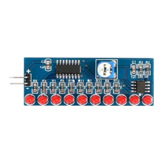
- Page 15 9) Your circuit board should look like this if you have proceeded up to step 8. 10) This kit provides a single row 2-pin header that can be used to power up the module. You can solder them if you have access to jumper wires or a pair of alligator clips. Otherwise, solder two pieces of wire to the positive (+) and the negative (-) leads on the board.
- Page 16 13) When your running flow LED module is turned ON, grab a small flat head screw driver and adjust the variable resistor (R4) to set the speed of the running LEDs. 14) You have completed the assembly of your module. For more Educational D.I.Y. Kits visit www.abra-electronics.com/educational-kits-trainers/...
Need help?
Do you have a question about the AK-72 and is the answer not in the manual?
Questions and answers