Table of Contents
Advertisement
Quick Links
FRANCE
SAMES Technologies. 13 Chemin de Malacher 38243 Meylan Cedex
Tel. 33 (0)4 76 41 60 60 - Fax. 33 (0)4 76 41 60 90 - www.sames.com
USA
SAMES Technologies Inc. 11998 Merriman Road, Livonia, Michigan, 48 150
Tel. (734) 261.5970 - Fax. (734) 261.5971 - www.sames.com
Index revision : G
From February 1st, 2017 SAMES Technologies SAS becomes SAMES KREMLIN SAS
A partir du 1/02/17, SAMES Technologies SAS devient SAMES KREMLIN SAS
User manual
Automatic mode of operation
This product is protected by French patents N° 2724787 et 2724786 which
have been extended to cover Europe and the United States.
GNM 100-A
1
6102
Advertisement
Table of Contents

Subscribe to Our Youtube Channel
Related Manuals for SAMES KREMLIN GNM 100-A


Summary of Contents for SAMES KREMLIN GNM 100-A
- Page 1 From February 1st, 2017 SAMES Technologies SAS becomes SAMES KREMLIN SAS A partir du 1/02/17, SAMES Technologies SAS devient SAMES KREMLIN SAS User manual GNM 100-A Automatic mode of operation This product is protected by French patents N° 2724787 et 2724786 which have been extended to cover Europe and the United States.
- Page 2 Any communication or copying of this document, in any form whatsoever, and any use or divulging of its contents is forbidden without express written permission from SAMES Technologies. The descriptions and characteristics contained in this document may be changed without prior warning and are in no way binding on SAMES Technologies.
-
Page 3: Table Of Contents
2.2.5. GNM 100-A module ........6... -
Page 4: Introduction
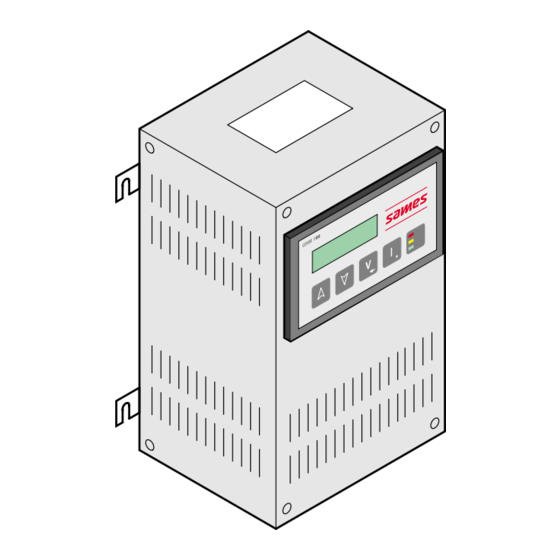
“high voltage units”. The controller has to be used with SAMES high voltage units. The model referred as the GNM 100-A is enclosed in a ventilated case which conforms to IP 20, refer- ence number 858224. The “ A ” version is for the installation of racks and electrical control panels. -
Page 5: Specifications
Input voltage 220 VAC +/- 20 V or 110 VAC + / - 20 V Frequency 50 / 60 Hz Max input power for GNM 100-A 80 VA ~ 15 k Ω Impedance 0 - 10 V 2.2.2. Electrical output data... -
Page 6: Gnm 100-A Module
2.2.5. GNM 100-A module 12- pin plug (high voltage unit) 19- pin plug (PLC) 7- pin plug (atomizer) 3. Operating principle WARNING : Screens given herein are provided only as examples. 3.1. Automatic high voltage unit selection WARNING : The GNM periodically checks for the presence and type of high voltage unit with which it is connected. -
Page 7: Menus
3.2. Menus After having recognized the high voltage unit, the GNM gives access to the menus. 3.2.1. User menu This is displayed as follows: The last line of the screen displays the GNM 's oper- ating mode. Means the module is in User Menu T = Type of trigger: int = internal - ext. -
Page 8: Calibrating Menu
Voltage set point Voltage Return • P5 = 1 triggering called «external». «Discrete I/o» (dry contact, 12 or 24 V depending on type of connection, see § 4.5 page 17) for hard wiring diagrams. Trigger Voltage set point Voltage Return 3.2.1.4. - Page 9 To have access to the calibrating menu, press keys 4 and 5 at the same time until the following screen appears: The calibration menu permits access for adjustment of the GNM parameters. Access to the menu is done by means of a 4-number code. The "FATORY" code is «1111».
- Page 10 Trigger Di/Dt soft is Disabled Set point Voltage Voltage Return RP3 : Di/Dt Soft Ramp Function This is a switch, which enables the Di/Dt soft thresh- old value to be in proportion to time. The effect of this switch is a greater amount of sensitivity, lower threshold value, during the initial few milliseconds when the high voltage is triggered.
- Page 11 3.2.2.6. Parameter P9: Fault Accept by External Trigger This parameter is a switch to authorize the recovery from a fault by the external trigger, available only if P5 = 0. 3.2.2.7. Parameter P15: High Voltage Value Correction This parameter can be used to adjust the displayed voltage on the front panel to correlate to the meas- ured high voltage at the applicator tip.
- Page 12 3.2.2.9. How to change the code in the calibration menu The last stage of the calibrating menu permits entry into a personal code. The screen displays: Follow the procedure see § 3.2.2.1 page 9 If the code ‘0000’ is entered, no code is requested from the operator between the user menu and the calibrating menu.
-
Page 13: Return To "Factory" Parameters
3.2.3. Return to «Factory» parameters It is possible to return to the factory parameters as follows: • Power off generator • Press simultaneously on keys 4 and 5 Power on unit • The GNM displays the software version • Release keys 4 and 5 •... -
Page 14: Limit Trip - I Limit Trip
The following message is displayed, for example: 3.3.2. V limit trip - I limit trip These errors indicate that at a certain moment, the voltage measured or the current measured has exceeded the maximum adjustment points of the high voltage unit for Vmax and Imax. 3.3.3. -
Page 15: Di / Dt
4.2. Low voltage connectors WARNING : see RT Nr 6169 for use with a high voltage unit UHT 153. 4.2.1. GNM 100-A module Connecting plug (12 pins) Connecting plug (19 pins) Connecting plug (7 pins) 4.3. Connecting plug (12 pins A) Connection to the high voltage unit. -
Page 16: Connecting Plug (7 Pins C)
4.4. Connecting plug (7 pins C) Connection to the controls of the atomizer (e.g. electro valve). It is possible to use the 4, 5 and 6-pins (trigger copy for the PLC). N° of Signal pins earth phase 1, output protected phase 2, output protected common to trigger image relay trigger image relay contact normally closed... -
Page 17: Connecting Plug (19 Pins B)
4.5. Connecting plug (19 pins B) Connection to an PLC: N° of pins Signal Earth Not connected Not connected Input 4 / 20 mA Earth 4 / 20 mA or 0 / 10 V Input 0 / 10 V Image output Vm (100 kV = ~ 5 V) Earth Image output Im (500 µA = ~ 5 V) Input + photo coupler... -
Page 18: Control Of Vm And Im Outputs
4.5.1.2. 0/10 V adjustment point Scale setting is done inside the GNM. 10 V corresponds to 100 kV. For a high voltage unit on which the maximum voltage is below 100 kV, the adjustment point is automatically reveled at its maximum value. 4.5.2. -
Page 19: Using Information Relative To The Faults
Supply return 12 to 24 V Inside GNM + 12 to 24 V dc 10 to 13 GNM case WARNING : Inputs 10 and 13 are opto-coupled inputs. They are therefore isolated from the earth. Make sure that the 0 V of the 12 to 24 V supply is at a potential close to the earth. 4.5.3.3. - Page 20 Liaison wiring with an PLC: Inside GNM PLC input 14 to 16 GNM case Wiring of a HV fault signalling lamp: Inside GNM 220 VAC oR 110 VAC Fault 14 to 16 GNM case Indice de révision : G 6102...
-
Page 21: List Of Parameters
5. List of parameters (diagrams in this chapter to be taken only as guide lines) Change in values of Change in values of Next screen or value Last screen/special parameters (Inc.) (2) parameters (Dec.) (3) validation (4) function (5) Same high voltage unit as last start up ? yes. - Page 22 Di / Dt soft function MP3=1 Di / Dt soft programming enabled MP3=0 Di / Dt soft programming disabled Adjustment of parameter P3. Adjustment of parameter SP3. Adjustment of parameter RP3. Adjustment of parameter P4. Adjustment of parameter P6. Adjustment of parameter P8. Adjustment of parameter P9, available only if P5 = 0 Adjustment of parameter P15.
- Page 23 Current management MP19 = 1 Current management by Fault MP19 = 0 Current management by Limitation Adjustment of parameter SP19. Adjustment of parameter TP19. Adjustment of parameter RP19. Modify the calibrating menu code, see § 3.2.2.1 page 9 Return to user menu. Index revision : G 6102...
-
Page 24: Trouble Shooting
6. Trouble shooting GNM no power, display and green LED off. GNM powered, display and green LED on. Power on. GNM Yes. Turn the GNM off for a minute then on again. GNM power on, display and green LED on. Replace the GNM. - Page 25 Check the low voltage cable. Fault CC Problem with low voltage cable? Yes. Replace the low voltage cable. Check the connector's low voltage termi- nals. Problem with the connector terminals ? Repair the low voltage terminals. Replace the GNM. GNM warning ? GNM working.
- Page 26 Check the low voltage cable ? Problem with low voltage cable ? Yes. Defective low voltage cable. Check the connector low voltage termi- nals. Defective connector terminal ? Repair / replace the low voltage termi- nals. Replace GNM. Has the problem disappeared? GNM working.
- Page 27 Adjust P19 at 0 and activate with trigger. In service, the system has already worked correctly, but current consumption has increased. Yes. Adjust Il at maximum value. Maintenance necessary for the HV sys- tem: the paint hose becomes conductive, air arrival circuit. Remove the HV from the high voltage unit if this is the case.
- Page 28 Target distance to close. Yes. Greater target distance required. Fault condition at start up ? In service, the system has already worked correctly. Check HV cable connections if this is the case. - length -HV contact -sufficient quantity of dielectric grease - black part of cable earthed? Problem solved ? Adjust parameter P3.
- Page 29 Measure the HV level at high voltage unit output. Above 20 kV difference between Vm and measure? Carry out same controls for excess of I or Di/Dt. Yes. Check low voltage cable. Problem with low voltage cable? Replace / repair the low voltage cable. Check the low voltage connections.
-
Page 30: Gnm References
Ref. Part number Description Sold in units of 858224 GNM 100-A - metal case (110-220V) 8. Plugs Ref. Part number Description Sold in units of E4PTFS316 Male plug 7 contacts E4PTFS343 Male plug 12 contacts E4PTFS406 Female plug 19 contacts...
Need help?
Do you have a question about the GNM 100-A and is the answer not in the manual?
Questions and answers