Table of Contents
Advertisement
Quick Links
Advertisement
Table of Contents

Related Manuals for Joy-it PSG 9080


Summary of Contents for Joy-it PSG 9080
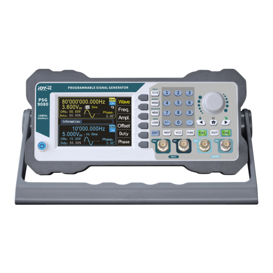
- Page 1 PSG 9080 Programmable signal generator...
-
Page 2: Table Of Contents
1. TABLE OF CONTENTS General information Safety instructions Overview front and rear side Function keys Screen overview Basic first steps Modulation mode Measuring mode Sweep mode 10. Voltage Control Mode (VCO) 11. Programming mode 12. System settings 13. Troubleshooting 14. Additional information 15. -
Page 3: Safety Instructions
2. SAFETY INSTRUCTIONS Please observe the following safety instructions before operating the unit in order to avoid damage to the unit and the connected devices, as well as injuries! unit operated with dangerous voltage, Never open the casing when it is connected to the power supply. There is a risk of electric shock! To avoid short-circuiting or electric shock, only use a suitable mains cable. -
Page 4: Overview Front And Rear Side
3. OVERVIEW FRONT AND REAR SIDE ⑥ ⑧ ⑦ ⑩ ⑨ ⑤ ④ ① ③ ② Number Description Number Description On-off button Rotary encoder + button Signal inputs Numeric keypad Signal outputs Function keys Channel control buttons Menu keys Direction buttons, Home button LC Display Number Description... -
Page 5: Function Keys
4. FUNCTION KEYS The function keys (front side no. 8): SYS: The system settings key. It is used to quickly switch between the main menu • and the system settings. - Press this button to open the settings menu and then press the menu button Page to move to the next page. - Page 6 FUNC: The function key. It is used to quickly switch between the main menu and • the programming mode. - Press FUNC to enter programming mode. Press the MODE menu button to switch between Normal Mode and Debug Mode. Button: The Home button. •...
-
Page 7: Screen Overview
5. SCREEN OVERVIEW Number Description Number Description Menu buttons Frequency Finger cursor Amplitude Current channel status Offset Phase Duty cycle Waveform display Information box 1.: The menu buttons display the operation menu of the currently selected function. 2.: The current finger cursor is on the CH1 interface, this means that the currently selected channel is CH1 and the change of parameters is only valid for this channel. -
Page 8: Basic First Steps
6.: Press the Freq. menu key to select "Frequency", use the direction keys to select the value you want to edit, then turn the knob to change the value. You can also change the value by en- tering it using the numeric keypad and then pressing the corresponding menu button to select the unit. - Page 9 To select the output channel: Press the CH1 or CH2 channel control button to select the CH1 or CH2 channel. You can see which channel is currently selected by the finger cursor. Select the waveforms: Press the Wave menu button. The menu button bar on the right side of the screen shows the waveform.
- Page 10 Set the amplitude: Press the Ampl. menu button to highlight "Amplitude" and use the numeric keypad or turn the knob to set the desired amplitude value. The amplitude range is limited by the frequency setting. The higher the frequency, the smaller the output amplitude range.
-
Page 11: Modulation Mode
7. MODULATIONSMODUS The PSG9080 can output modulated waveforms in single or dual channels. Modulation is the process of processing the information from the signal source and adding it to the carrier to make it suitable for channel transmission. It is the technology that changes the carrier with the signal. - Page 12 Amplitude modulation is a modulation method in which the amplitude of the carrier wave changes according to the desired transmission signal, but the frequency remains unchanged. Setting the modulation depth: The modulation depth indicates the degree of amplitude change, expressed as a percentage. The range of the amplitude modulation depth can be set from 0% to 200%.
- Page 13 Phase-shift keying (PSK): With phase-shift keying, the phase of the output signal is shifted by the set phase, depending on the logic level of the source signal. Setting the polarity: Press the Polar menu key to select the amplitude of the modulated wave controlled by "positive polarity"...
-
Page 14: Measuring Mode
Set the number of pulses: Press the Num. menu button to set the number of pulses. Use the numeric keyboard or the direction keys and the rotary knob to enter the desired num- ber of pulses. The number of pulses ranges from 1 to 100000000, the default is 1. 8. -
Page 15: Sweep Mode
Counting function The counting function calculates the number of input signal periods in real-time. Set the coupling: Press ▲ ▼ to set the cursor to coupling. Use the rotary knob to switch the coupling between AC and DC. After setting the coupling, you can press the ON button to start the counting function. Press the OFF button to stop, the RST menu button to restore the default settings and the Save menu button to save the parameters. - Page 16 Sweep Frequency Press the FUNC menu button to select the Sweep Frequency function. (S.Freq) Start frequency and end frequency: The start frequency and the end frequency are the upper and lower frequency limits of the fre- quency sweep. You can set both with the direction keys and the rotary knob, or the numeric keypad.
- Page 17 10. VOLTAGE CONTROL MENU (VCO) VCO stands for voltage-controlled oscillator. A voltage-controlled oscillator is an electrical oscillator whose frequency can be changed by the magnitude of an applied voltage. Press VCO and the FUNC menu key to select the frequency control, amplitude control and duty cyc- le control functions.
-
Page 18: Programming Mode
Turn on VCO amplitude: Press the ON button to activate the function. The amplitude change can be observed on the dis- play. VCO Duty Cycle Press the FUNC button in the voltage control menu to select the duty cycle control (V.Duty). Start duty cycle and end duty cycle: The start duty cycle and end duty cycle are the upper and lower limits of the duty cycle's duty cycle. -
Page 19: System Settings
GoTo The value in the GoTo field indicates the number of the instruction to jump to. If the value in the GoTO field is 05, it is transferred to instruction no. 05 after the current instruction is com- pleted to start the run. Loop The value in the field indicates how often the instruction is repeated;... - Page 20 Change page: Press the PgDn menu button to access the second page of the system settings. Waveform synchronization: The waveform synchronization can be switched on and off via the menu keys ON and OFF, or the rotary knob. During synchronization, the parameters of the CH2 channel change with the parameters of the CH1 channel.
-
Page 21: Troubleshooting
13. TROUBLESHOOTING This chapter lists the common PSG9080 errors and their solutions. If you encounter these problems, please solve them by following the appropriate steps. If the problem persists, plea- se contact us. The screen is still dark (no display) after pressing the power button: Check whether the power supply is connected correctly. -
Page 22: Additional Information
SIMAC Electronics GmbH, Pascalstr. 8, D-47506 Neukirchen-Vluyn, Germa- Possibility of return in your area: We will send you a parcel stamp with which you can return the device to us free of charge. Please contact us by email at Service@joy-it.net or by telephone. Information on packaging: If you do not have suitable packaging material or do not wish to use your own, please contact us and we will send you suitable packaging.
Need help?
Do you have a question about the PSG 9080 and is the answer not in the manual?
Questions and answers