Advertisement
Available languages
Available languages
Quick Links
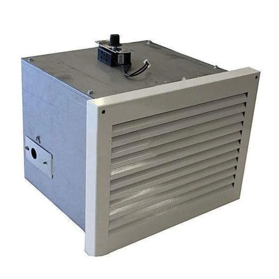
INSTALLATION INSTRUCTIONS FOR MODEL HDX52
ENSURE THE UNIT IS COMPLETELY COOL BEFORE STARTING INSTALLATION
TO AVOID DANGER OF SUFFOCATION KEEP THE PACKAGING BAG AWAY FROM BABIES AND CHILDREN.
DO NOT USE IN CRIBS, BED, CARRIAGES OR PLAY PENS. THIS BAG IS NOT A TOY. KNOT BEFORE
CONSUMER: RETAIN THESE INSTRUCTIONS FOR FUTURE REFERENCE.
WARNING: UNPLUG ALL ELECTRICAL CONNECTIONS BEFORE BEGINNING WITH INSTALLATION.
ELECTRICAL CONNECTIONS MUST BE MADE BY A CERTIFIED ELECTRICIAN.
NOTE: Consideration should be made for blower location as the closer to the
appliance, the greater the air fl ow noise will be.
A.
For wire harness installation remove the lock washer and nut that secure the
blower to the blower housing. Remove the blower from the housing by lifting
up and out, as shown.
B.
Connect the wire harness to the left side of the blower.
C.
Loosen the nut that secures the junction box to the blower housing.
Remove the junction box, as shown.
D.
Guide the end of the wire harness through the bushing in the junction box
and then through the junction box plate.
E.
Re-install the junction box.
F.
Re-install the blower.
G.
Position the blower to an inside wall into a framed opening 12
high, as shown below.
NOTE: The blower housing should be installed onto a level surface large enough to support the blower assembly
for dimensions. Allow for fi nishing material when securing the blower housing, as the grill mounts to the
housing. Ensure the blower is oriented properly with the footings of the blower housing at the bottom, refer to
the illustration below.
INSTALLER: LEAVE THESE INSTRUCTIONS WITH THE APPLIANCE.
10.25"
12.25"
NZ64 & GA65
WARNING
!
THROWING AWAY.
3
/
" wide by 10
8
1.25"
14.25"
10.75"
10.75"
Footings
Footings
A
C
JUNCTION
BOX
1
/
"
2
1
10
/
"
2
JUNCTION BOX
COVER PLATE
W415-1320 / 06.26.14
Advertisement

Related Manuals for Napoleon NZ64


Summary of Contents for Napoleon NZ64
- Page 1 NZ64 & GA65 INSTALLATION INSTRUCTIONS FOR MODEL HDX52 WARNING ENSURE THE UNIT IS COMPLETELY COOL BEFORE STARTING INSTALLATION TO AVOID DANGER OF SUFFOCATION KEEP THE PACKAGING BAG AWAY FROM BABIES AND CHILDREN. DO NOT USE IN CRIBS, BED, CARRIAGES OR PLAY PENS. THIS BAG IS NOT A TOY. KNOT BEFORE THROWING AWAY.
- Page 2 Remove the junction box covers from both the appliance and the blower housing. Remove the blower panel from the right or left side of the appliance. Connect the 6” collar to the blower connection opening. Secure the collar by reaching through and bending the tabs back. The opening that is not being used should be covered, if not already, with the blower panel that is provided.
- Page 3 NZ64 & GA65 INSTRUCTIONS D’ INSTALLATION POUR MODÈLE HDX52 AVERTISSEMENT ASSUREZ-VOUS QUE L’APPAREIL EST COMPLÈTEMENT REFROIDI AVANT DE COMMENCER L’INSTALLATION. AFIN D’ÉVITER LES RISQUES DE SUFFOCATION, GARDEZ LE SAC D’EMBALLAGE LOIN DES BÉBÉS ET DES JEUNES ENFANTS. NE LE LAISSEZ PAS TRAÎNER DANS LES BERCEAUX, LES LITS, LES POUSSETTES OU LES PARCS DE JEU.
- Page 4 Retirez les couvercles des boîtes de dérivation de l’appareil et du boîtier de la souffl erie. Retirez le panneau de recouvrement du côté droit ou gauche de l’appareil. Insérez le collet de 6” dans l’ouverture pour la souffl erie. Fixez le collet en accédant l’intérieur de celui-ci et en pliant les pattes. L’ouverture qui n’est pas utilisée doit être couverte, si ce n’est déjà...