Advertisement
Table of Contents
- 1 Table of Contents
- 2 Warning Decal Placement
- 3 Important Precautions
- 4 Before You Begin
- 5 Part Identification Chart
- 6 Assembly
- 7 How to Use the Treadmill
- 8 How to Fold and Move the Treadmill
- 9 Maintenance and Troubleshooting
- 10 Exercise Guidelines
- 11 Part List
- 12 Exploded Drawing
- 13 Ordering Replacement Parts
- 14 Recycling Information
- Download this manual
Model No. PFTL59420-INT.0
Serial No.
Write the serial number in the space
above for reference.
Serial
Number
Decal
CUSTOMER SERVICE
UNITED KINGDOM
Call: 08457 089 009
From Ireland: 053 92 36102
Website: www.iconsupport.eu
E-mail: csuk@iconeurope.com
Write:
ICON Health & Fitness, Ltd.
Unit 4, Westgate Court
Silkwood Park
OSSETT
WF5 9TT
UNITED KINGDOM
AUSTRALIA
Call: 1800 993 770
E-mail: australiacc@iconfitness.com
Write:
ICON Health & Fitness
PO Box 635
WINSTON HILLS NSW 2153
AUSTRALIA
CAUTION
Read all precautions and
instructions in this manual before
using this equipment. Keep this
manual for future reference.
USER'S MANUAL
iconeurope.com
Advertisement
Table of Contents

Related Manuals for ProForm 505 CST


Summary of Contents for ProForm 505 CST
- Page 1 Model No. PFTL59420-INT.0 Serial No. Write the serial number in the space USER’S MANUAL above for reference. Serial Number Decal CUSTOMER SERVICE UNITED KINGDOM Call: 08457 089 009 From Ireland: 053 92 36102 Website: www.iconsupport.eu E-mail: csuk@iconeurope.com Write: ICON Health & Fitness, Ltd. Unit 4, Westgate Court Silkwood Park OSSETT...
-
Page 2: Table Of Contents
Note: The decals may not be shown at actual size. PROFORM and IFIT are registered trademarks of ICON Health & Fitness, Inc. App store is a trademark of Apple Inc., registered in the U.S. and other countries. Android and Google Play are trademarks of Google LLC. The Bluetooth ®... -
Page 3: Important Precautions
IMPORTANT PRECAUTIONS WARNING: To reduce the risk of burns, fire, electric shock, or injury to persons, read all important precautions and instructions in this manual and all warnings on your treadmill before using your treadmill. ICON assumes no responsibility for personal injury or property damage sus- tained by or through the use of this product. - Page 4 19. When a person is walking on the treadmill, 24. Do not change the incline of the treadmill by the noise level of the treadmill will increase. placing objects under the treadmill. 20. Keep fingers, hair, and clothing away from 25.
-
Page 5: Before You Begin
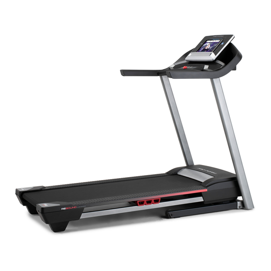
® 505 CST manual. To help us assist you, note the product model treadmill. The 505 CST treadmill provides an impres- number and serial number before contacting us. The sive selection of features designed to make your model number and the location of the serial number workouts at home more effective and enjoyable. -
Page 6: Part Identification Chart
PART IDENTIFICATION CHART Use the drawings below to identify small parts used for assembly. The number in parentheses below each draw- ing is the key number of the part, from the PART LIST near the end of this manual. The number following the key number is the quantity used for assembly. -
Page 7: Assembly
ASSEMBLY • Assembly requires two persons. • To identify small parts, see page 6. • Place all parts in a cleared area and remove the • Assembly requires the following tools: packing materials. Do not dispose of the packing the included hex keys materials until you fi... - Page 8 2. Make sure that the power cord is unplugged. Remove the tie securing the Upright Wire (88) to the front of the Base (97). Next, identify the Right Upright (86). Have a second person hold the Right Upright near the Base (97).
- Page 9 4. Set the Right Upright (86) on the Base (97) as shown. Make sure not to pinch the Upright Wire (88). Slide the Right Upright so that the 3/8" x 2 3/8" Screw (3) in the Base is inserted into the slot (E) in the Right Upright; do not fully tighten the Screw yet.
- Page 10 6. Attach a Handrail (80) to the Right Upright (86) with two 5/16" x 1 1/2" Screws (7) and two 5/16" Star Washers (12) in the location shown; start both Screws, and then tighten them. Make sure not to pinch the Upright Wire (88), and make sure that the wire is on the indicated side of the Upright.
- Page 11 8. With the help of a second person, hold the con- sole assembly (G) near the Right Upright (86). Next, insert the Upright Wire (88) through the indicated looped tie (48) and connect it to the console wire (H). The connectors should slide together easily and snap into place.
- Page 12 10. IMPORTANT: To avoid damaging the Crossbar (87), do not use power tools and do not overtighten the #10 x 3/4" Screws (6). Attach the Crossbar (87) to the Handrails (80) with four #10 x 3/4" Screws (6) and four #10 Star Washers (10);...
- Page 13 12. Tighten all eight indicated Screws (1, 2, 3). 1, 2, 3 1, 2, 3 13. Note: If the treadmill is assembled on a smooth surface, it may roll forward during this step. Raise the Frame (60) to the upright position. IMPORTANT: Do not raise the Frame past the vertical position.
- Page 14 14. Remove the 5/16" Nut (39) and the 5/16" x 1 3/4" Bolt (28) from the bracket on the Base (97). Next, orient the Storage Latch (35) as shown. Attach the lower end of the Storage Latch (35) to the bracket on the Base (97) with the 5/16"...
-
Page 15: How To Use The Treadmill
HOW TO USE THE TREADMILL HOW TO PLUG IN THE POWER CORD Follow the steps below to plug in the power cord. This product must be earthed. If it should malfunc- 1. Plug the indicated end of the power cord (A) into the tion or break down, earthing provides a path of least socket on the treadmill (B). - Page 16 CONSOLE DIAGRAM FEATURES OF THE CONSOLE You can even listen to your favorite workout music or audio books with the console’s sound system while you The treadmill console offers a selection of features exercise. designed to make your workouts more effective and enjoyable.
- Page 17 HOW TO TURN ON THE POWER HOW TO USE THE MANUAL MODE IMPORTANT: If the treadmill has been exposed to 1. Insert the key into the console. cold temperatures, allow it to warm to room tem- perature before you turn on the power. If you do See HOW TO TURN ON THE POWER at the left.
- Page 18 5. Follow your progress with the display. To turn off the scan mode, press the Display button; the scan indicator and the word SCAN will The display can show the following workout turn off. information: You can also customize the scan mode to display Calories (CALS)—The approximate number of only the desired workout information in the calories you have burned.
- Page 19 HOW TO USE AN ONBOARD WORKOUT The workout will continue in this way until the last segment ends. The walking belt will then 1. Insert the key into the console. slow to a stop. See HOW TO TURN ON THE POWER on page 17. If the speed or incline setting for the current seg- ment is too high or too low, you can manually over- 2.
- Page 20 HOW TO CONNECT YOUR TABLET TO THE 5. Disconnect your tablet from the console if CONSOLE desired. The console supports Bluetooth connections to tablets To disconnect your tablet from the console, first via the iFit—Workouts at Home app and to compatible select the disconnect option in the iFit—Workouts heart rate monitors.
- Page 21 THE SETTINGS MODE Display Test—This screen is intended to be used by service technicians to identify whether the 1. Select the settings mode. display is working correctly. To select the settings mode, press Button Test—This screen is intended to be used the gear button (K).
- Page 22 Demo Mode—The currently selected demo mode THE OPTIONAL TABLET HOLDER option will appear in the display. The console features a demo mode, designed to be used if the The optional tablet treadmill is displayed in a store. If the demo mode holder (L) will hold is turned on, the console will not turn off and the your tablet securely...
-
Page 23: How To Fold And Move The Treadmill
HOW TO FOLD AND MOVE THE TREADMILL HOW TO FOLD THE TREADMILL HOW TO MOVE THE TREADMILL To avoid damaging the treadmill, adjust the incline Before moving the treadmill, fold it as described at the to zero before you fold the treadmill. Then, remove left. -
Page 24: Maintenance And Troubleshooting
MAINTENANCE AND TROUBLESHOOTING MAINTENANCE c. Check the power switch located on the treadmill frame near the power cord. If the switch protrudes Regular maintenance is important for optimal per- as shown (A), the switch has tripped. To reset the formance and to reduce wear. Inspect and properly power switch, wait for five minutes and then press tighten all parts each time the treadmill is used. - Page 25 SYMPTOM: The displays of the console do not SYMPTOM: The walking belt slows when walked on function properly a. If an extension cord is needed, use only a 3-conduc- a. Remove the key from the console and UNPLUG tor, 14-gauge (2 mm ) cord that is no longer than THE POWER CORD.
- Page 26 SYMPTOM: The walking belt is not centered SYMPTOM: The walking belt slips when walked on between the foot rails a. First, remove the key and UNPLUG THE POWER IMPORTANT: If the walking belt rubs against CORD. Using the hex key, turn both idler roller the foot rails (D), the walking belt may become screws clockwise, 1/4 of a turn.
-
Page 27: Exercise Guidelines
EXERCISE GUIDELINES Aerobic Exercise—If your goal is to strengthen your WARNING: cardiovascular system, you must perform aerobic Before beginning this exercise, which is activity that requires large amounts or any exercise program, consult your physi- of oxygen for prolonged periods of time. For aerobic cian. - Page 28 SUGGESTED STRETCHES The correct form for several basic stretches is shown at the right. Move slowly as you stretch —never bounce. 1. Toe Touch Stretch Stand with your knees bent slightly and slowly bend forward from your hips. Allow your back and shoulders to relax as you reach down toward your toes as far as possible.
- Page 29 NOTES...
-
Page 30: Part List
PART LIST Model No. PFTL59420-INT.0 R0820A Key No. Qty. Description Key No. Qty. Description 3/8" x 1 1/4" Screw Walking Belt 3/8" x 1 1/2" Screw Belt Guide 3/8" x 2 3/8" Screw Rubber Cushion #8 x 3/4" Screw 1/2" Pin #8 x 1/2"... - Page 31 Key No. Qty. Description Key No. Qty. Description Base Magnet Left Tray Clamp Right Tray M4 Nut Console Base M4 x 10mm Bolt Console Frame Motor Bushing Console Ground Wire Motor Isolator Reed Switch – User’s Manual Note: Specifications are subject to change without notice. For information about ordering replacement parts, see the back cover of this manual.
-
Page 32: Exploded Drawing
EXPLODED DRAWING A Model No. PFTL59420-INT.0 R0820A... - Page 33 EXPLODED DRAWING B Model No. PFTL59420-INT.0 R0820A 38 33...
- Page 34 EXPLODED DRAWING C Model No. PFTL59420-INT.0 R0820A 2 11...
- Page 35 EXPLODED DRAWING D Model No. PFTL59420-INT.0 R0820A 101 27...
-
Page 36: Ordering Replacement Parts
ORDERING REPLACEMENT PARTS To order replacement parts, please see the front cover of this manual. To help us assist you, be prepared to provide the following information when contacting us: • the model number and serial number of the product (see the front cover of this manual) •...
Need help?
Do you have a question about the 505 CST and is the answer not in the manual?
Questions and answers