
Subscribe to Our Youtube Channel
Related Manuals for Nexen RSTC1000


Summary of Contents for Nexen RSTC1000
- Page 1 WEB CONTROL PRODUCTS User Manual Tension Controller RSTC1000 FORM NO. L-21204-D-0418...
- Page 2 They must not be put into service until the machinery into which it is to be incorporated has been declared in conformity with the provisions of the Directive mentioned above or its amendments. All Nexen products are designed in accordance with the manufacturing directives for pneumatic systems ac- cording to EN 983.
-
Page 3: Table Of Contents
Table of Contents Introduction ----------------------------------------------------------------------------------------------------------------------------------------4 Wiring Installation Guidelines --------------------------------------------------------------------------------------------------5 Installation -----------------------------------------------------------------------------------------------------------------------------6 Electrical Connections ------------------------------------------------------------------------------------------------------------7 Network Connections -----------------------------------------------------------------------------------------------------10 Input/Output Descriptions -----------------------------------------------------------------------------------------------11 Setup --------------------------------------------------------------------------------------------------------------------------------- 13 RSTC to PC USB Communications ---------------------------------------------------------------------------------13 Display Window --------------------------------------------------------------------------------------------------------------13 Setup Window ----------------------------------------------------------------------------------------------------------------13 Torque Actuator --------------------------------------------------------------------------------------------------------------14 Tension Zone ------------------------------------------------------------------------------------------------------------------14 Alarms ---------------------------------------------------------------------------------------------------------------------------15 Web ------------------------------------------------------------------------------------------------------------------------------15 Outputs -------------------------------------------------------------------------------------------------------------------------15... -
Page 4: Introduction
INTRODUCTION Nexen RSTC Tension Controllers are used to control web tension, relying on load cell based tension sensors to measure web tension. As a part of a tension control system, the RSTC measures the web’s tension and corrects tension errors by sending a signal to change the torque output of brakes, clutches, and motor drive systems. -
Page 5: Wiring Installation Guidelines
WIRING INSTALLATION GUIDELINES This product is designed to minimize the effects of ElectroMagnetic Interference (EMI) on its operation, but as with any electronic device, proper installation and wiring methods are necessary to ensure proper operation. By doing so, the interference from external effects such as electrical line spikes, electrical noise, static electricity, etc. will be minimized. -
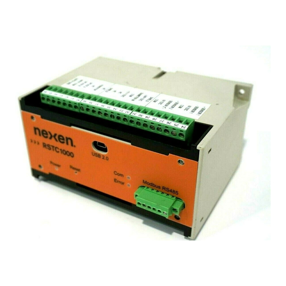
Page 6: Installation
INSTALLATION Mount the RSTC within a user-supplied enclosure, typically CAUTION the machine’s controls cabinet. The RSTC can be mounted Mount the RSTC in a shock and vibration free on 35 mm DIN rail or panel mounted (Refer to Figure 3). area with an ambient temperature of less than 140°F [60 C] and more than 32°F [0 C]. -
Page 7: Electrical Connections
ELECTRICAL CONNECTIONS Power Indicator Reset Network Port and Indicators +24 VDC Control Signal Shield & Earth Ground** † Power Common Control Signal Common Input* Earth Ground** Splice B Input Splice A Input Control Alarm 1 Out Inputs Alarm 2 Out Run/Stop Input Alarm Common †... - Page 8 User Supplied VD C* (See Specifications for maximum voltage.) (See Note.) RSTC To PL C Input Alarm Out Alarm VD C Common Common User Supplied NOTE: The minimum value of resistor (R) is 7 x VDC. Alarm Output Tied to PLC Input. User Supplied External Indicator (See Note.)
- Page 9 40 41 42 43 44 45 46 32 33 34 35 36 37 38 39 Cable Shields DC Common Run/Stop 1–5 kΩ +12 to + 24 VDC Potentiometer Splice B NOTE: Potentiometer can be replaced with analog Splice A voltage signal by connecting analog signal (0-12V NOTE: To isolate the Control Input Signals, use a power maximum) to terminal 37 and signal common to supply that is separate from the RSTC power supply.
-
Page 10: Network Connections
NETWORK CONNECTIONS Modbus RS485 Port: This port is for communicating with ROP - RSTC the RSTC1000 using the Modbus RTU protocol over a 2-wire or 4-wire RS485 physical layer (Refer to Figure 10). RSTC Communication Indicator: Yellow indicator, visible +24 VDC... -
Page 11: Input/Output Descriptions
INPUT/OUTPUT DESCRIPTIONS The alarm outputs can be isolated from the RSTC power NOTE: Refer to Figure 4 for RSTC Pinout. supply by using a separate power source and common. Alarm Common is the return line for the alarm signal. Alarm USB Port: This port is used to connect to a personal Shield is the terminal for connecting the alarm cable shield computer during setup, tuning, or diagnostic monitoring... - Page 12 INPUT/OUTPUT DESCRIPTIONS (CONT.) scaled such that 0 V or 4 mA corresponds to Minimum Tension Setpoint and 10 V or 20 mA corresponds to Maximum Tension Setpoint. If Control Output B is being used as a web tension monitoring output, then it is not available for use as a web tension control output.
-
Page 13: Setup
RSTC Communications Software are required. A Type A to mini Type B 2.0 USB cable is provided with the RSTC. RSTC Communications Software is available by Network Port and download from Nexen’s website, www.nexengroup.com. Indicators Figure 11 Enter RSTC product number (See PART NUMBER section) in the product number search window and press Go;... -
Page 14: Torque Actuator
DISPLAY icon and then selecting Imperial or Metric in the UNITS pane. Inertia values for Nexen Brakes and Clutches can be found in the Nexen catalog or website. For drive systems, enter the mo- tor rotor, drive pulley, and shaft coupling inertias. -
Page 15: Alarms
ALARMS NOTE: A web break is detected whenever the web tension falls below 10% of the Maximum Tension Setpoint Alarm 1 is used to signal the break. Tension Tolerance: Enter the tolerance (0–100 %) of the tension setpoint to establish the limits for the High Tension and Low Tension alarms. -
Page 16: Signal Calibration
SIGNAL CALIBRATION SIGNAL CALIBRATION WINDOW Select the SIGNAL CALIBRATION icon from the toolbar. (See Figure 17). TENSION SIGNAL CALIBRATION Set the Maximum Tension Setpoint before calibrating tension sensors. Afterwards, re-calibration of tension sensors is required whenever the Maximum Tension Setpoint is changed. Minimum Tension Setpoint: Enter minimum tension level that will be run on the machine in the designated imperial or metric units. -
Page 17: Diameter Signal Calibration
DIAMETER SIGNAL CALIBRATION 1. Press DIAMETER (See Figure 20). 2. Press Yes if a diameter signal is present and continue with calibration. Press No if there is not a diameter signal, therefore the calibration procedure will not continue. 3. Enter the core diameter and large roll diameter that will be used for calibration. - Page 18 Ignal oMentary ulsed nCoder When the Start/Stop input signal pulses high, the RSTC The first time a machine driven encoder pulses Run/Stop algorithm will begin adapting to account for the roll’s diam- input, the RSTC algorithm will begin adapting to account eter and inertia.
-
Page 19: Tuning
TUNING TUNING WINDOW Select the TUNING icon from the toolbar. (See Figure 23). Note: After changing values, the SEND key must be pressed to send the values to the RSTC. Gain: Adjusts response of RSTC to magnitude changes in tension. Higher values cause a more aggressive response and lower values cause a lesser response. -
Page 20: Setpoint
SETPOINT Remote SP: Select ON to enable tension setpoint Tension Setpoint: Enter the desired web tension level. by external analog signal (See I N PUT/OUTPUT The Tension Setpoint range is set by the Maximum and DESCRIPTIONS section) or OFF to disable this feature. Minimum Tension Setpoint values in the Setup window. -
Page 21: Network Port Setup
Modbus master device. If connecting to Nexen’s RSTC Operator Panel, select 2. RSTC Device Address: Specify the device address required by the Modbus master device. If connecting to Nexen’s RSTC Figure 26 MODBUS Port Setup Screen Operator Panel, select 24. -
Page 22: Unwind Application
This shortens the time it takes for the RSTC1000 to adapt its gains to the new roll. During a machine stop, Adaptation and Output values will initially increase to overcome a roll’s inertia. After a Stop... -
Page 23: Wind Application
WIND APPLICATION During a machine stop, Adaptation and Output values A typical winding application begins at core. The INITIAL ADAPTATION value should be set high enough to allow will initially increase to overcome a roll’s inertia. It is the tension setpoint to be reached quickly after the Run normal for the RSTC to remain in Run mode throughout signal is given. -
Page 24: Spring Disengaged Clutch
MID-PROCESS APPLICATION SPRING DISENGAGED CLUTCH Nexen’s RSTC is capable of mid-process tension control It is common to use a spring-disengaged clutch on a winder by adjusting the torque output of a motor or brake. Mid- and this spring can affect performance if the RSTC’s output process applications are similar to an unwind process becomes too low and the clutch begins to disengage. -
Page 25: Specifications
Control Output 2 0-10 VDC and 4-20 mA SENSOR EXCITATIONS Load Cell Excitation 6 VDC Other Sensor Excitations 24 VDC @ 100 mA max & 12 VDC @ 60 mA CERTIFICATIONS Certification PART NUMBERS RSTC1000 (Modbus RTU Network) 964523 FORM NO. L-21204-D-0419... -
Page 26: Troubleshooting
TROUBLESHOOTING Problem Probable Cause Diagnosis Test Corrective Action Check for 24 VDC across Power Indicator is not No power terminals 1 and 2 using a Restore 24 VDC. illuminated. voltmeter. Correct any problems with Control inputs do not Measure the voltage at inputs voltage or wiring using the Improper or missing signal respond. -
Page 27: Service Instructions
SERVICE INSTRUCTIONS Nexen does not recommend customer servicing of this product. Contact Nexen for replacement parts or repair. APPENDIX To determine WK of a normal shaft or disc, multiply The value of WK is important for applications involving the WK... -
Page 28: Warranty
Buyer shall be obligated to pay or which Buyer may incur based upon, related to or arising out of its contracts with its customers or other third parties. In no event shall Nexen be liable for any amount of damages in excess of amounts paid by Buyer for Products or services as to which a breach of contract has been determined to exist.
Need help?
Do you have a question about the RSTC1000 and is the answer not in the manual?
Questions and answers