Advertisement
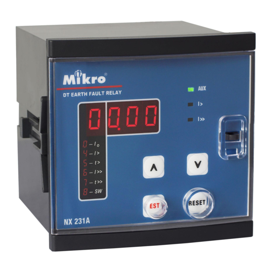
8. CASE DIMENSIONS
96 mm
Front
90mm
Figure 2: Case Dimensions
110mm
100mm
NX231A Earth-fault Relay User's Guide
start/
start/
1. DESCRIPTION
The NX321A is a microprocessor based
numerical earth-fault relay. It uses
fundamental
frequency
current
measurement for excellent harmonic
current rejection. The relay provides
two-element (low-set and high-set)
earth-fault protection with definite time
characteristic. The 4-digit LED indicator
on the NX231A allows the display of
present load current; recorded fault
current for last tripping; and all setting of
the relay
Rev M0 (04/19)
2. LIGHT INDICATORS
The indicators display the status of the system as follow:
Indicator
Aux l> l>> FUNC DT
Status
0
0
0
0
0
No Auxiliary power supply.
1
0
0
X
X
Normal condition, no tripping.
1
1
0
X
X
Low-set overcurrent triggered,
time delay countdown started.
1
0
1
X
X
High-set overcurrent triggered,
time delay countdown started.
1
B
0
B
B
Low-set tripped,
DT digit shows tripped value.
1
0
B
B
B
High-set tripped,
DT digit shows tripped value.
1
X
X
1
B
Programming mode.
Table 1: System Status
1 = ON
0
= OFF
X= don't care, not blinking
B = blinking DT = DATA
FUNC = FUNCTION
Advertisement
Table of Contents

Subscribe to Our Youtube Channel
Related Manuals for Mikro NX231A


Summary of Contents for Mikro NX231A
- Page 1 The 4-digit LED indicator High-set overcurrent triggered, on the NX231A allows the display of time delay countdown started. present load current; recorded fault Low-set tripped, current for last tripping; and all setting of DT digit shows tripped value.
- Page 2 Accuracy 4. OUTPUT CONTACTS Protection thresholds ....± 5% a) Trip test The NX231A has two sets of output contact: Time delay.........± 5% with a mimimum of 50ms Press and hold the “TEST” key for 3.5 seconds to (i) CONTACT R1 - linked to trip signal.
Need help?
Do you have a question about the NX231A and is the answer not in the manual?
Questions and answers