Table of Contents
Advertisement
Quick Links
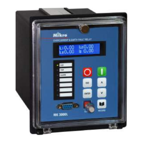
Combined Overcurrent and Earth Fault Relay
3 stages phase overcurrent and earth fault
IDMT and definite time
Thermal overload protection
Trip circuit supervision
RS232 and RS485 MODBUS-RTU communication
Fault, alarm and event records with timestamp
Disturbance records
Inrush blocking
CB Maintenance
Multi-shot autoreclose
Negative sequence overcurrent
Circuit breaker open/close control
Programmable LED
Advertisement
Table of Contents

Subscribe to Our Youtube Channel
Related Manuals for Mikro MK 3000L


Summary of Contents for Mikro MK 3000L
- Page 1 Combined Overcurrent and Earth Fault Relay 3 stages phase overcurrent and earth fault IDMT and definite time Thermal overload protection Trip circuit supervision RS232 and RS485 MODBUS-RTU communication Fault, alarm and event records with timestamp Disturbance records Inrush blocking CB Maintenance Multi-shot autoreclose Negative sequence overcurrent Circuit breaker open/close control...
-
Page 2: Table Of Contents
Table of Contents 1.0 Introduction ......................3 1.1 Symbols and Definitions ......................3 1.2 Main Functions .......................... 4 2.0 Front Panel ......................5 2.1 LCD Display ..........................5 2.2 Keypad ............................5 2.3 LEDs ............................6 2.4 RS232 Port ..........................6 2.5 Default Display .......................... -
Page 3: Introduction
1.0 Introduction The purpose of this manual is to provide information necessary to install, operate and maintain the Mikro MK3000L relay. MK3000L provides protections for 3 independent phase overcurrent elements and one non- directional earth-fault element. All these elements are connected to the current transformers of the feeders to be protected. -
Page 4: Main Functions
1.2 Main Functions The following table shows the functions available for MK3000L ANSI codes Features 50P/51P Three-phase overcurrent 50N/51N Earth fault overcurrent 49RMS Thermal overload (True RMS) Negative sequence overcurrent Cold load pickup Instantaneous/start contact Latching output contacts Setting groups 50BF Circuit breaker failure detection 74TC... -
Page 5: Front Panel
2.0 Front Panel Using the front panel, the user can easily navigate through the user friendly menu, read measurements and change settings. The relay status and alarm or trip records are displayed on the back-lit LCD also. LCD Display Fixed function Programmable Keypad... -
Page 6: Leds
Open CB : To open circuit breaker from front panel. Close CB : To close circuit breaker from front panel. 2.3 LEDs Aux LED : Indicates auxiliary power to the device Trip LED : Indicates tripping. Alarm LED : Blinks to indicate non acknowledge alarm (or tripping). Steady on when the alarm is acknowledged by pressing any key Programmable LED : 4 Programmable LED can be programmed to turn on when one or more... -
Page 7: Password
subsequently next records until all the records are shown and repeats. Each page is shown for 5 seconds. Example when there are 2 alarm records: Record 1 Title Page Record 1 Sub Page Record 2 Title Page Record 2 Sub Page Record 1 Title Page …. -
Page 11: Measurements Menu
MEASUREMENTS Menu Various measurement values can be read under MEASUREMENTS menu. (The values are shown for illustrative purpose). Heading of MEASUREMENTS menu. Press Enter to enter submenu 1.MEASUREMENTS content. Displays phase 1 current value. Taking into account of Phase CT Pri ratio. -
Page 12: Records Menu
Displays average phase 1 current value. IL1 Avg 323A Displays average phase 2 current value. IL2 Avg 80.4A Displays average phase 3 current value. IL3 Avg 78.2A Displays average earth current value. Io Avg 6.24A To clear the maximum and average values of the currents. Press Clear Max &... - Page 13 Fault record sub page 3, showing L1 current during fault. Press IL1 Magnitude Up/down to change sub page. Press Esc/Enter to return to Fault 4.86A Record title page. Fault record sub page 4, showing L2 current during fault. Press IL2 Magnitude Up/down to change sub page.
-
Page 14: Configuration Menu
CONFIGURATION Menu Heading of CONFIGURATION menu. Press Enter to enter submenu 3.CONFIGURATION content. Op parameter Menu Heading of Op Parameter submenu. Press Enter to enter submenu 3.1 Op Parameter content. This password is required when changing relay settings. Press Enter to Password enter a new password. - Page 15 disturbance record current scaling only. Note: The CT secondary should be connected to 5A or 1A CT input terminal according to the CT secondary current rating. The display current is calculated by the formula: Current at CT input terminal / CT input terminal type x CT Pri (setting above) For example: Current at CT input terminal = 3A, Current at CT input terminal = 3A,...
- Page 16 Display Menu Heading of Display menu. Press Enter to enter submenu content. 3.5 Display Set how long the LCD backlight remains on after no key is pressed. LCD On Time Press Enter to change. 10min Set the brightness of the LCD backlight. Press Enter to change. LCD Brightness Medium Set if Clear key can be used (during no alarm or trip state) to scroll...
-
Page 17: Protection G1 Menu
Io>>? Assigned Io>> start to LED tIo>>? Assigned tIo>> trip to LED Io>>>? Assigned Io>>> start to LED tIo>>>? Assigned tIo>>> trip to LED tI2>? Assigned I2> start to LED tI2>>? Assigned tI2> trip to LED Input 1? Assigned Input 1 status to LED Input 2? Assigned Input 2 status to LED Aux 1? - Page 18 If Definite Time is selected, the following menu is displayed: Set the value for the time delay of I> definite time. tI> 1.00s If IDMT is selected, the following menu is displayed: Set the type of curve. I> IDMT Curve Normal Invrse Set the time multiplier setting value for the curve.
- Page 19 Io> menu Set to Yes to enable earth fault first threshold (Io>). Then the Io>? following menu is displayed. Set the value for the current threshold Io>. Io> NOTE : When delay type is IDMT, the maximum setting 0.10Ion recommended should be 0.5Ion.. Set the time delay type of Io>.
- Page 20 Set the value for the current threshold Io>>>. Io>>> 20.0Ion Set the value for the time delay of Io>>> definite time. tIo>>> 30ms Neg Seq OC Heading of Neg Seq OC (Negative Sequence Overcurrent) menu. 4.3 Neg Seq OC Press Enter to enter submenu content. I2>...
- Page 21 Set the value for the time delay of I2>> definite time. tI2>> 100ms Thermal OL Menu Heading of Thermal OL (Overload) menu. Press Enter to enter 4.4 Thermal OL submenu content. Set to Yes to enable thermal overload protection. Then the following Thermal OL? menu is displayed.
-
Page 22: Protection G2 Menu
Set the dead time for reclose cycle 3. Dead Time 6.00s Set the dead time for reclose cycle 4. Dead Time 10.00s Set the reclaim time. . The reclaim time starts when the CB has closed Reclaim Time (52A input activates). If no tripping after reclaim time elapsed, the 8.00s autoreclose resets. - Page 23 Heading of Input 1 menu. Press Enter to enter submenu content. 6.1 Input 1 Set the function of Input 1. Setting choices are: None, Aux 1, Aux 2, Input 1 Func Reset, Blocking, TCS, Select Group, Cold Load PU (pickup) and Aux 1 Sync Clock, CB Status 52A, Blk Autoreclose, Control Close, Start Dist Rcrd, Local...
-
Page 24: Output Menu
If Reset is selected, the following menu is displayed: Rst Trip/Alarm Set to yes to enable the input to reset trip and alarm. Rst Thermal θ% Set to yes to enable the input to reset thermal %. If Blocking is selected, the following menu is displayed: Block I>? Set to yes to enable blocking of I>... - Page 25 tI>>>? Assign I>>> trip to the output relay. tIo>? Assign Io> trip to the output relay. tIo>>? Assign Io>> trip to the output relay. tIo>>>? Assign Io>>> trip to the output relay. Thml OL? Assign Thermal Overload to the output relay. tAux 1? Assign Aux 1 input trip to the output relay.
-
Page 26: Communication Menu
tAux 1(Alarm)? Yes Assign Aux 1 input alarm to the output relay. tAux 2(Alarm)? Yes Assign Aux 2 input alarm to the output relay. TCS(Alarm)? Yes Assign TCS alarm to the output relay. Demand(Alarm)? Yes Assign Demand alarm to the output relay. I2>? Yes Assign I2>... -
Page 27: Misc Control Menu
Set to yes to enable MODBUS RTU communication. Communication? Set to yes to enable setting change through communication. When set Remote Set? to no, only Reset alarm/trip, Reset maximum and average measure- ment value, Reset display, and change of date and time is allowed. Set the baud rate in bit per second (bps). - Page 28 Displays the summation of the current (in Amps or square Amps, set Amps(n) IL1 Σ by ‘n’ in CB Alarm menu) for phase 1 interrupted by the circuit 345 kA breaker. Same as above for phase 2 Amps(n) IL2 Σ 12 kA Same as above for phase 3 Amps(n) IL3...
- Page 29 Set the summation of the current (in Amps or square Amps) threshold. ΣAmps(n) 100MA Amps. 1 (IA) or 2 (I Σ Set the exponent for the summation for Inr Blocking Heading of Inrush Blocking menu. Press Enter to enter submenu 9.3 Inr Blocking content Set to Yes to enable the crossing of the 2...
- Page 30 Scaling value, in percent, for the cold load pick up assigned to the CLPU Level selected thresholds. 200% Delay timer setting (tCL) for the Cold Load Pickup function. CLPU tCL 5.00s The following protection functions can be assigned to cold load PU. CLPU I>? Assign I>...
-
Page 31: Functions And Descriptions
5.0 Functions and Descriptions 5.1 Circuit Breaker Failure Protection Circuit breaker failure protection (CBFP) is used to generate a tripping signal via selected output relay after a preset time delay if the fault has not been cleared after the activation of tripping signal through trip contact relay R1. -
Page 32: Thermal Overload Protection
5.3 Thermal Overload Protection Thermal overload protection can be used to prevent damages to the equipment of the electrical plant. A prolonged overloading causes excessive heating, which may result in deterioration of the insulation, or in extreme cases, insulation failure. Load current is used to calculate the heating and cooling effect of the equipment to be protected. -
Page 33: Trip Circuit Supervision
5.4 Trip Circuit Supervision Trip Circuit Supervision (TCS) enables the trip circuit to be monitor. To enable TCS function, set one of the Digital Input function to TCS (at the INPUT Menu), Input Type as Active High and set the appropriate TCS delay time. The continuity of trip circuit is monitor when Trip contact R1 is not energized. - Page 34 Examples 3: Trip Coil and Auxiliary Contacts Monitoring when CB is open or closed In this example both 52a and 52b auxiliary contacts are available; the complete trip circuit is monitored when the CB is open or closed. In this case it is necessary to insert resistor R1, if the Trip contact R1 is latched or it stays involuntarily closed.
-
Page 35: Disturbance Recorder
5.5 Disturbance Recorder The disturbance recorder can be initiated by starting, tripping, input or remote (disturbance). The total disturbance recording time is 6 records of 3 seconds, or 4 × 4s, or 3 × 5s, or 2 × 7s or 1 × 9s. When the available memory space is used up, the new record automatically overwrites the oldest record. -
Page 36: Open Cb & Close Cb Control
Lockout Reset After lockout the CB can be closed by control close input, CB close button or remote CB close command or by manual CB Close. The inhibit timer starts counting after CB close (52A input activates). When the timer elapsed, lockout condition reset. Block Autoreclose Input If this input activate during reclose cycle , recloser locks out. -
Page 37: Characteristic Curves
Characteristic Curves Normal Inverse Very Inverse Long-time Inverse Normal Inverse 1.3/10 0.05... - Page 38 Extremely Inverse Thermal Overload Curves (k=1.1, T =10minutes) θ time/second 10,000 1,000 Initial thermal state I / I θ...
-
Page 39: Case Dimensions
6.0 Case Dimensions 7.0 Connection Diagram and Terminal 7.1 Terminal Connection at Rear View... - Page 40 Connection terminal Function Description 5A / 1A common CT input for I 5A CT input for I 1A CT input for I 5A / 1A common CT input for I 5A CT input for I 1A CT input for I 5A / 1A common CT input for I 5A CT input for I 1A CT input for I...
-
Page 41: Typical Connection Diagram
7.2 Typical Connection Diagram Example 1: With neutral. CT secondary 5A. Uaux Trip Contact MK3000L Internal Relay Failure Termination Resistor Digital Input 1 RS485 Digital Input 2 Communication cable shield Series resistor 18k Ohm, 2W Shorting terminal 18 and 20 required for >170 Vac / 240 Vdc for the last relay to 270Vac / 380Vdc... -
Page 42: Technical Data
8.0 Technical Data RATINGS Auxiliary Supply MK3000L-150D Rated voltage : 30 ~ 120 V DC Operating voltage : 24 ~ 150 V DC MK3000L-240AD Rated voltage : 100 ~ 240 V AC or 140 ~ 340 V DC Operating voltage : 85 ~ 265 V AC or 110 ~ 370 V DC Rated frequency : 50 or 60Hz... - Page 43 SETTING RANGES General Phase CT primary : 1 to 10000 A. 1 to 1000: step 1; 1000 to 10000: step 5 Phase CT Secondary, In : 1 or 5 A Earth CT primary : 1 to 10000 A. 1 to 1000: step 1; 1000 to 10000: step 5 Earth CT Secondary, Ion : 1 or 5 A Frequency : 50 or 60 Hz...
- Page 44 Normal Inverse 1.3/10 ktI2 : 0.01 to 1.00 I2>>? : Yes or No I2>> : 0.1 to 40 x In. *Variable steps tI2>> : 0 to 100 s. *Variable steps Thermal Overload Thermal OL? : Yes or No Iθ> : 0.1 to 3.00 x In. *Variable steps : 1 to 200 minutes.
- Page 45 Stop Bit : 1 or 2 Relay Address : 1 to 255 CB Alarm CB Opening Time? : Yes or No CB Opening Time : 0.05 to 1s CB Closing Time? : Yes or No CB Closing time : 0.05 to 1s CB Operations? : Yes or No CB Operations...
- Page 46 Negative sequence Is ± 5% or 30mA 0.1 to 40 x In 0.95 x Is ± 3% DT: ±2% +30ms overcurrent, whichever greater IDMT: ±6% +30ms I2> (>1.2 x Is) 0.1 to 3 x In ±5% Thermal overload, Iθ> INSULATION High voltage dielectric withstand test IEC60255-5 : 2kV rms, 1 minute High voltage impulse test IEC60255-5...
-
Page 47: Modbus Protocol
MODBUS Protocol Both of the RS232 port on the front panel and the RS485 port on the rear terminals use MODBUS RTU protocol. The RS232 front panel port is fixed to 38400bps, even parity, 1 stop bit, relay address 1. The RS485 rear port communication setting is set by the COMMUNICATION Menu from the front panel. - Page 48 0x10 Write Multiple Registers Request Communication address 1 byte 0* to 255 Function code 1 byte 0x10 Starting Address 2 bytes 0x0000 to 0xFFFF Quantity of Registers 2 bytes 0x0001 to 0x007b (N) Byte count 1 byte 2 X N Register value N X 2 bytes Value...
-
Page 49: Modbus Register
9.2 MODBUS Register *Note: For MK3000L, Device type – main is 00 02 03. Device type –sub is 00. Parameter Format Units and Scale Range Address Product information. Read only. Function 03h or 04h 0000 ASCII '00' Device type - main* 0001 ASCII '02'... - Page 50 Parameter Format Units and Scale Range Address LCD backlight on duration minute 1 - 60 020D LCD backlight brightness 020E 0=low, 1=medium, 2=high Clear' key to scroll settings 020F 0=No, 1=Yes 0210 Communication? (Unused) 0=No, 1=Yes 0211 Communication Baud Rate 0=2400, 1=4800, 2=9600, 3=19200, 4=38400 0212 Communication Parity...
- Page 51 Parameter Format Units and Scale Range Address Protection Group 1 0300 Thermal Overload? 0=Disable, 1=Enable 0.01 In 10 - 300 (0.1-3) 0301 Thermal Full Load Current, Iθ 0302 Thermal Time Constant, Tθ minute 1 - 200 0303 Thermal Factor, k 0.01 100-150 (1-1.5) 0304...
- Page 52 Fault Record Parameter Format Units and Range Address Scale Fault Records. Read only. Function 03h or 04h 4096 1000 Fault Record 1 4097 1001 Fault Record 2 4145 1031 Fault Record 50 Each Fault Record consists of 16 words: Fault record words Word Number Description Format...
- Page 53 Event Record Parameter Format Units and Range Address Scale Event Records. Read only. Function 0x03 or 0x04 8192 2000 Record 1 8193 2001 Record 2 8441 20F9 Record 250 Alarm Records. Read only. Function 0x03 or 0x04 12288 3000 Record 1 12289 3001 Record 2...
- Page 54 Steps to read Disturbance records: 1. Read 3100 to find out number of disturbance records available 2. Select one of the record number and channel by reading 3200-3705. 3. Read from 4000 the selected record number and channel until total number in the mapping read. 4.
- Page 55 Address Parameter Format Units and Scale Range Selection of disturbance record and channel. Read only. Function 0x03 or 0x04. Only 1 address being read at a time. 12800 3200 Record number 1, IL1 12801 3201 Record number 1, IL2 12802 3202 Record number 1, IL3 12803...
- Page 56 Digital input and outputs channel: 16 Bits word Bit 0: Input 1 Bit 1: Input 2 Bit 2-Bit 7: Unused Bit 8: Output Relay 1 Bit 9: Output Relay 2 Bit 10: Output Relay 3 Bit 11: Output Relay 4 Bit 12-Bit 14: Unused Bit 15: Output Relay IRF IL1, IL2, IL3 channel multiplier: This value divided by 204800 to get channel multiplier.
-
Page 57: Modbus Mapping Format
9.3 MODBUS Mapping Format CODE DESCRIPTION 2 bytes ASCII character Unsigned integer – Relay status Bit 0: Eeprom data failure Bit 11: Back port (RS485) unread fault record Bit 1: Calibration failure Bit 12: Front panel (RS232) unread fault record Bit 2: Clock loss Bit 13: Front panel/Back port communication Bit 3: Clock error... - Page 58 Unsigned integer A scaled numeric value of certain units Eg. 123 may represent 1.23A or 1.23s Refer to individual resisger's 'Units and Scale' and 'range' for detail Unsigned integer – Cold Load Pick-up element Bit 0: tI> Bit 5: tIo>>> Bit 1 tI>>...
- Page 59 Unsigned integer – Disturbance record number 0=None 1=6 Records X 3 seconds 2=4 Records X 4 seconds 3=3 Records X 5 seconds 4=2 Records X 7 seconds 5=1 Records X 9 seconds Unsigned integer – Autoreclose Cycle Allocation Cycles 4 3 2 1 X X X X (bit 0-1:cycle 1, 2-3: cycle 2, 4-5: cycle 3, 6-7 cycle 4) Where X equals to:...
Need help?
Do you have a question about the MK 3000L and is the answer not in the manual?
Questions and answers