Table of Contents
Advertisement
Quick Links
1. Installing the SVMi-20E in an OfficeServ 7200/7400 Series System
When installing an SVMi-20E card, it is important to remember that it is a computer, much the same as any
desktop PC and it is therefore very important not to exceed the environmental limits of an ordinary PC.
POWER REQUIREMENTS
I
Because the SVMi-20E card does NOT draw from the -48DC supply it has a Zero (0) SEPU rating under all
possible configurations.
OfficeServ 7200/7400 Series HARDWARE COMPATIBILITY
I
When configured for 16 ports or less this card can be installed in any universal slot. When configured for
20 ports the SVMi-20E card must be installed in 32 channel slots.
OfficeServ 7200/7400 Series SOFTWARE COMPATIBILITY
I
All versions of the OfficeServ 7200/7400 support the SVMi-20E operation. We have introduced a new 8-
Port VPM daughterboard to reach the 20 ports that requires SVMi-20E software version 5.3.3.5 or higher
and MP software version 4.30h or higher.
2. Inspection
Unpack and inspect the unit for any obvious damage. This card should be labeled SVMi-20E. If it is not, you
have the wrong card. Before inserting the SVMi-20E card in the OfficeServ system install required optional
boards to meet customer's configuration and requirements.
3. Installing Individual Components on SVMi-20E SBC
3.1 Installing Voice Processing Modules
VPMs are only necessary when more than 4 ports are required on the SVMi-20E.VPMs are NOT required
to access the first four embedded ports. Adding new VPMs is as simple as plugging them with the cor-
rect location for each module. Here is a chart showing the correct location and VPM for this installation.
Configuration
1
2
3
4
5
6
7
8
9
10
SVMi-20E Installation / May 2009
SVMi-20E INSTALLATION
Included on
VPM in SL2
SBC
4
none
4
VPM-E
4
VPMF-E
4
VPM-E
4
VPM-E
4
8VPMF-E
4
VPMF-E
4
8VPMF-E
4
8VPMF-E
4
8VPMF-E
VPM in SL3
Total Ports
none
4 Voice
none
8 Voice
none
8 Voice Supporting 1 Fax
VPM-E
12 Voice
VPMF-E
12 Voice Supporting 1 Fax
none
12 Voice Supporting 1 Fax
VPMF-E
12 Voice Supporting 2 Fax
VPM-E
16 Voice Supporting 1 Fax
VPMF-E
16 Voice Supporting 2 Fax
8VPMF-E
20 Voice Supporting 2 Fax
Home Page
1
Advertisement
Table of Contents

Related Manuals for Samsung SVMI-20E


Summary of Contents for Samsung SVMI-20E
- Page 1 1. Installing the SVMi-20E in an OfficeServ 7200/7400 Series System When installing an SVMi-20E card, it is important to remember that it is a computer, much the same as any desktop PC and it is therefore very important not to exceed the environmental limits of an ordinary PC.
-
Page 2: Installation
VPM installation. Discharge any static electricity you may have gathered by touching a ground point such as the cover of the KSU Power Supply. When you have done this then lay the SVMi-20E card face up on a non-conductive surface. - Page 3 System. Discharge any static electricity you may have gathered by touching a ground point such as the cover of the KSU Power Supply. When you have done this then lay the SVMi-20E card face up on a non-conductive surface. After you have either followed the above steps for an existing installation or if you have a brand new SVMi-20E ready to add the 64MB DRAM Module, follow the steps outlined in this docu- ment in either the “Removing a Hard Disk Drive”or “Removing the Compact Flash (CF) Adaptor”...
- Page 4 The final step is to do a proper shut down on the SVMi-20E and once a t a C:> press the reset button on the front of the SVMi-20E. (Steps for performing a proper shut down are described in the section Correct System Shutdown.)
-
Page 5: Installing A Hard Disk Drive (Hdd)
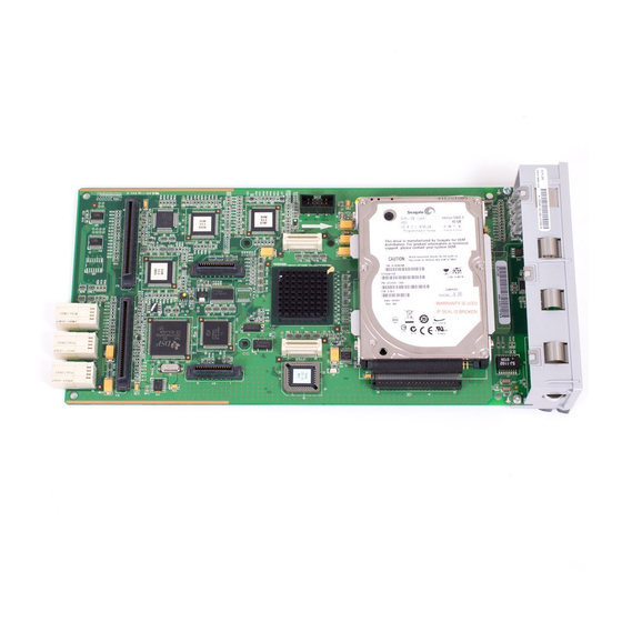
6. Inserting or Removing a Compact Flash Adapter 6.1 Removing the Compact Flash (CF) Adapter 1. Do a proper shut down of the SVMi-20E. (Steps for performing a proper shut down are described in the section Correct System Shutdown.) 2. Power down the phone system and remove the SVMi-20E card. - Page 6 Home Page The SVMi-20E displayed on the left has all optional boards installed; (2) VPMF-Es, (1) Modem, (1) DRAM Module (this is located directly under the Compact Flash Controller). Also shown are the SVMi-20E Compact Flash Controller and 256MB Compact Flash Media.
-
Page 7: Power Up Procedure
After inserting the SVMi-20E card and turning the power on there are some key system options that should be set, in order for the SVMi-20E to function correctly. These steps are performed in the phone system. It is necessary to perform these at this time so that the SVMi-20E will initialize properly and synchronize its mail- box database with that of the key system. -
Page 8: Testing The Hardware
1. From any phone on the system Log into KMMC Programming 2. Using MMC 740 change RESTART SVM from “No” to “Yes” 3. The SDN LED on the front of the SVMi-20E will change from RED to Green. Green means it is safe to power down the switch. - Page 9 3. Select 'Exit the SVMi-20E' 4. Enter System Administrator's password (Default = 0000) 5. The SDN LED on the front of the SVMi-20E will change from RED to Green. Green means it is safe to power down the switch. †...
- Page 10 Home Page 9.1.1 LOCAL PROGRAMMING VIA SIO Connect the serial port of the SVMi-20E unit to the serial port of the laptop or terminal using a direct RJ-45 Male to 9 pin female DB9 connector cable. The Pin out for making your own cable is as follows:...
- Page 11 Terminal operation: Open an Xmodem file receive window. (Transfer/Receive Xmodem). RX - Move a file from the PC attached to the SVMi-20E Serial Port to the SVMi-20E. Syntax: RX [path] filename. Where [path] filename represents where the destination file will be sent on the SVMi-20E.
- Page 12 IP address of the SVMi-20E. This can only be done using the SIO connection described previ- ously in this document. Using the SIO interface you will do a proper shut down of the SVMi-20E. Once at a C:> DOS prompt press the Reset button the front of the SVMi-20E face plate. Watch the boot up sequence and you will be asked to select a boot up option (the Default is: 1 –...
- Page 13 Now type in the new address required by your specific net- work. (an example might be 192.168.25.33) In the above example the SVMi-20E IP address would be 192.168.25.33.That is the address other devices on the network would use to reference or communicate with the SVMi-20E.
- Page 14 11. You will now be at the C:\Sockets> DOS prompt. 12. Now press the RED reset button on the SVMi-20E and let the unit come up normally. † A # in front of a line in the Socket.CFG file tells the application to ignore, skip over, and NOT execute the line.
- Page 15 NOTE: All IP addresses used must be on the same network. If you change the SVMi-20E Static IP address then you MUST change the Default Gateway address. The DNS addresses can be skipped.
Need help?
Do you have a question about the SVMI-20E and is the answer not in the manual?
Questions and answers