Chapters
Table of Contents

Related Manuals for Bunn TU3Q-EZ


Summary of Contents for Bunn TU3Q-EZ
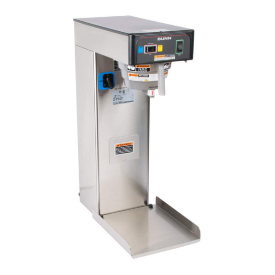
- Page 1 BUNN ® TU3Q-EZ OPERATING & SERVICE MANUAL BUNN-O-MATIC CORPORATION POST OFFICE BOX 3227 SPRINGFIELD, ILLINOIS 62708-3227 TELEPHONE: (217) 529-6601 FAX: (217) 529-6644 29460.0000C 8/00 © 1999 Bunn-O-Matic Corporation...
-
Page 2: Table Of Contents
REPAIR OR, AT BUNN’S SOLE OPTION, REPLACEMENT OR REFUND. In no event shall Bunn be liable for any other damage or loss, including, but not limited to, lost profits, lost sales, loss of use of equipment, claims of Buyer’s customers, cost of capital, cost of down time, cost of substitute equipment, facilities or services, or any other special, incidental or consequential damages. -
Page 3: User Notices
Carefully read and follow all notices on the equipment and in this manual. They were written for your protec- tion. All notices on the equipment should be kept in good condition. Replace any unreadable or damaged labels. #00831.0000 #00656.0000 #03408.0000 #03409.0000 USER NOTICES Page 3... -
Page 4: Electrical Requirements
" water supply line. A tight coil of copper tubing in the water line will facilitate moving the brewer to clean the countertop. Bunn-O-Matic does not recommend the use of a saddle valve to install the brewer. The size and shape of the hole made in the supply line by this type of device may restrict water flow. -
Page 5: Initial Set-Up
PLUMBING REQUIREMENTS (cont.) 1. Remove the shipping cap from the bulkhead fitting on the rear of the brewer. 2. Attach the flare fitting from the short piece of tubing on the strainer/flow control (supplied) to the water inlet fitting at the rear of the brewer. 3. -
Page 6: Operating Controls
CAUTION - DO NOT KEEP BREWED ICED TEA OVERNIGHT. THE SERVER MUST BE CLEANED DAILY. Begin each brew cycle with a clean empty brew funnel and server. (Be sure the server lid doesn’t interfere with the flow of dilution water.) Insert a BUNN ® filter into the funnel. -
Page 7: Adjustments And Optional Settings
TU3Q-EZ ADJUSTMENTS & OPTIONAL SETTINGS P1864 Adjusting Total Volume BREW VOLUME SET-UP: Use the following steps when setting up the brewer for the first time. 1. Place an empty funnel in the funnel rails and an empty vessel of at least 4 gallons beneath the funnel. -
Page 8: Troubleshooting
A troubleshooting guide is provided to suggest probable causes and remedies for the most likely problems encountered. If the problem remains after exhausting the troubleshooting steps, contact the Bunn-O-Matic Technical Service Department. • Inspection, testing, and repair of electrical equipment should be performed only by qualified service person- nel. - Page 9 TROUBLESHOOTING (cont.) BREWING CIRCUIT PROBLEM Ready light flashing Brew cycle will not start PROBABLE CAUSE 1. Brewer has shut down due to malfunction. 1. No water 2. No power or incorrect voltage to the brewer 3. ON/OFF switch not in the "ON" po- sition 4.
- Page 10 TROUBLESHOOTING (cont.) BREWING CIRCUIT (cont.) PROBLEM Consistently low beverage level in the dispenser or beverage over- flows dispenser Dripping from sprayhead PROBABLE CAUSE 1. Brew volume 2. Lime build up 3. Brew Solenoid Valve 4. Strainer/Flow Control 1. Lime build up 2.
- Page 11 Settings . See page 7 BUNN ® paper filters must be used for proper extraction. ® The BUNN paper filter must be centered in the funnel and the bed of tea leaves leveled by shaking gently. The brew funnel should be cleaned...
- Page 12 TROUBLESHOOTING (cont.) HEATING CIRCUIT (cont.) PROBLEM Water does not heat to proper temperature IMPORTANT: Make sure no tem- perature tests are taken before the ready light is "ON". Tank tempera- ture must be stabilized before read- ings are taken. Spitting or excessive steaming Brewer is making unusual noises PROBABLE CAUSE 1.
- Page 13 Intermittent flashing of the READY indicator indicates that a fault exists. Count the number of flashes between pauses and use this chart as a guide to investigating the fault. FLASHES CAUSE Dry Plug - In Fault - Sheath of temperature probe dry for 10 minutes after power-up Low Tank Level Fault - Level probe dry for 7 minutes after fill valve is energized Low Water Temperature Fault -...
-
Page 14: Service
SERVICE This section provides procedures for testing and replacing various major components used in this brewer should service become necessary. Refer to Troubleshooting for assistance in determining the cause of any problem. WARNING - Inspection, testing, and repair of electri- cal equipment should be performed only by qualified service personnel. -
Page 15: Brew Solenoid Valve
SERVICE (cont.) BREW SOLENOID VALVE FIG. 2 BREW SOLENOID VALVE Location: The brew solenoid valve is mounted on the left side in the bottom rear of the brewer. Test Procedures: 1. Disconnect the brewer from the power source. 2. Disconnect the white and white/green wires from the solenoid valve. -
Page 16: Limit Thermostat
SERVICE (cont.) LIMIT THERMOSTAT FIG. 4 LIMIT THERMOSTAT Location: The limit thermostat is located inside the hood on the tank lid. Test Procedure: 1. Disconnect the brewer from the power source and remove the blue wire from the limit thermostat. 2. -
Page 17: On/Off Switch
SERVICE (cont.) ON/OFF SWITCH FIG. 6 ON/OFF SWITCH Location: The ON/OFF switch is located in the front of the hood, above and to the left of the brew funnel. Test Procedure: 1. Disconnect the brewer from the power source. 2. Remove the black and white/violet wires from the switch terminals. -
Page 18: Start Switch
SERVICE (cont.) START SWITCH FIG. 8 START SWITCH Location: The start switch is located in the front of the hood, above and to the right of the brew funnel. Test Procedure: 1. Disconnect the brewer from the power source. 2. Remove the wires from the terminals. 3. -
Page 19: Tank Heater
SERVICE (cont.) TANK HEATER FIG. 10 TANK HEATER Location: The tank heater is located inside the tank and secured to the tank lid. Test Procedures: 1. Disconnect the brewer from the power supply. 2. With a voltmeter, check the voltage across the black and white wires. -
Page 20: Temperature Probe
SERVICE (cont.) TEMPERATURE PROBE FIG. 12 TEMPERATURE PROBE Location: The temperature probe is located on the tank rear of the tank lid, behind the tank heater. Test Procedures: 1. Disconnect the brewer from the power source. 2. Remove the temperature probe from the grom- met. -
Page 21: Control Board
SERVICE (cont.) CONTROL BOARD FIG. 14 CONTROL BOARD Location: The Control Board is located inside the hood on the right front behind the Start switch. Test Procedure: The test procedures for the control board will vary depending upon the problems experienced by the brewer. -
Page 22: Wiring Schematic
29460 082300 Page 22...
Need help?
Do you have a question about the TU3Q-EZ and is the answer not in the manual?
Questions and answers