Table of Contents
Advertisement
Chipsmall Limited consists of a professional team with an average of over 10 year of expertise in the distribution
of electronic components. Based in Hongkong, we have already established firm and mutual-benefit business
relationships with customers from,Europe,America and south Asia,supplying obsolete and hard-to-find components
to meet their specific needs.
With the principle of "Quality Parts,Customers Priority,Honest Operation,and Considerate Service",our business
mainly focus on the distribution of electronic components. Line cards we deal with include
Microchip,ALPS,ROHM,Xilinx,Pulse,ON,Everlight and Freescale. Main products comprise
IC,Modules,Potentiometer,IC Socket,Relay,Connector.Our parts cover such applications as commercial,industrial,
and automotives areas.
We are looking forward to setting up business relationship with you and hope to provide you with the best service
and solution. Let us make a better world for our industry!
Contact us
Tel: +86-755-8981 8866 Fax: +86-755-8427 6832
Email & Skype: info@chipsmall.com Web: www.chipsmall.com
Address: A1208, Overseas Decoration Building, #122 Zhenhua RD., Futian, Shenzhen, China
Advertisement
Table of Contents

Subscribe to Our Youtube Channel
Related Manuals for Linx Technologies TT Series

Summary of Contents for Linx Technologies TT Series
- Page 1 Chipsmall Limited consists of a professional team with an average of over 10 year of expertise in the distribution of electronic components. Based in Hongkong, we have already established firm and mutual-benefit business relationships with customers from,Europe,America and south Asia,supplying obsolete and hard-to-find components to meet their specific needs.
- Page 2 TT Series Master Development System User's Guide...
-
Page 3: Table Of Contents
TT Series Transceiver Carrier Board Objects NO OEM LINX REMOTE CONTROL OR FUNCTION MODULE SHOULD EVER BE USED IN LIFE AND PROPERTY SAFETY TT Series Transceiver Carrier Board Pin Assignments SITUATIONS. No OEM Linx Remote Control or Function Module Programming Dock should be modified for Life and Property Safety Situations. -
Page 4: Introduction
The Master Development System provides a designer with all the tools necessary to correctly and legally incorporate the TT Series into an end product. The boards serve several important functions: •... -
Page 5: Ordering Information
EVM Module Socket Kit NC 36 37 NC 56 NC Figure 2: Ordering Information Figure 4: TT Series Transceiver Carrier Board Pin Assignments (Top View) Programming Dock TT Series Transceiver Carrier Board Bottom Figure 3: TT Series Transceiver Carrier Board... -
Page 6: Remote Control Demo Board
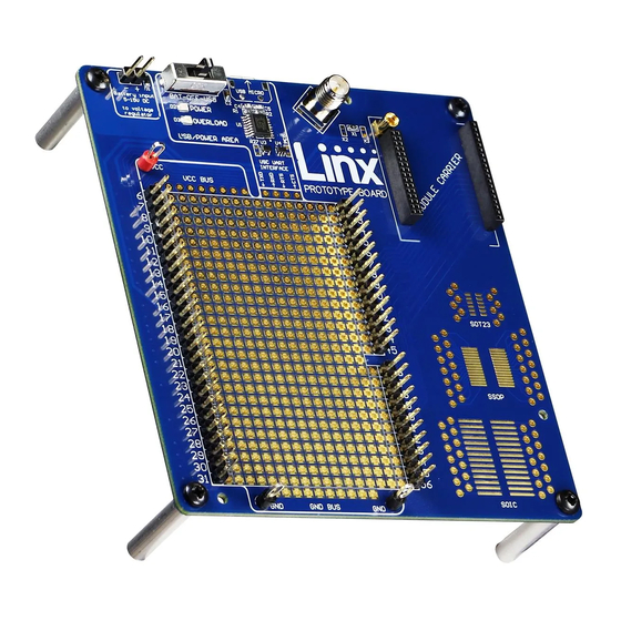
Remote Control Demo Board Prototype Board Board A Board B Figure 6: Remote Control Demo Board Figure 7: Prototype Board Remote Control Demo Board Objects Prototype Board Objects 1. Carrier Board Socket 1. Carrier Board Socket 2. RP-SMA Antenna Connector 2. -
Page 7: Initial Setup
Board A has the buttons on the right column and board B has them on the left column. These accept the Carrier Boards and are used to demonstrate the remote control functionality of the TT Series. They can also be used for range testing. These boards use hardware configuration, so if any changes have been made to the modules using the software then they may not operate correctly. -
Page 8: Using The Remote Control Demo Board
Using the Remote Control Demo Board Range Testing Several complex mathematical models exist for determining path loss in Snap a Carrier Board onto the socket on each Remote Control Demo many environments. These models vary as the transmitter and receiver are Board as shown in Figure 9. -
Page 9: Using The Prototype Board
Using the Prototype Board Supply for the module is connected through R17. This can be removed and replaced by another supply or used to measure the current consumption of Snap a Carrier Board onto the socket on the Prototype Board as shown in the module. -
Page 10: The Development Kit Demonstration Software
Programming Dock. The software defaults to the to the prototype board. The TT Series uses the pull-down resistor. Do Demo & EZConfiguration tab when opened (Figure 13). This window offers not populate both resistors at the same time as this results in a direct basic configuration and demonstration of the module’s functionality with the... - Page 11 The modules are shown with three identifiers as shown in Figure 14. Figure 14: The Master Development System Software Module Identifiers 1. The type of module (TT Series) 2. The module’s local address. 3. A custom name that can be given to the module. Type a name into the box and press Enter to apply it.
- Page 12 7. The Set Module button adds the address and Permissions Mask to The Command Set tab (Figure 17) allows specific commands to be written the list. If a current module is selected, then the Permissions can be to the module. updated.
- Page 13 6. The structure of the selected command and its response is shown connected module’s status is reflected in the software. in the main window. Please see the TT Series Transceiver Command Data Interface Reference Guide for definitions of each value.
-
Page 14: Development Kit Demonstration Software Example
Development Kit Demonstration Software Example This example shows how to configure two modules to work with each other. The software defaults to the Demo & EZConfiguration tab when opened (Figure 21). Figure 23: The Master Development System Software Pairing Modules Once the module is dropped into the Given Permissions window it is written to the active module’s memory. - Page 15 Changing the active module is accomplished by dragging a module from This tab shows the advanced configurations enabled by the module’s the Available list to the Active spot, as shown in Figure 25. Command Data Interface. Any changes are highlighted in red. In the example in Figure 27 the output mask has been changed to all inputs, S0 is latched, the Paired module is given full permissions, the status line direction is set by the mask and the outputs are latched by the Latch Mask.
- Page 16 Figure 28: The Master Development System Software Demo and EZConfiguration Tab with Changes Figure 30: The Master Development System Software Transmitting Module The buttons have all changed to LEDs. The symbol next to each LED indicates if it is latching or momentary (Figure 29). S0 is latching, the rest are momentary.
- Page 17 Full system operation is demonstrated by clicking on the Sandbox tab (Figure 32). Figure 34: The Master Development System Software Save Profile Once saved, the profile appears in the window, as shown in Figure 35. Figure 32: The Master Development System Software Sandbox These configurations can be saved as a profile for recalling or programming into other modules.
-
Page 18: Carrier Board Schematic
CMD_DATA_IN boards for multiple module families. Some circuitry is not applicable for some modules. RSSI RSSI POWER_DOWN RESTORE TRM-XXX-TT ICSPDAT ICSPCLK Figure 36: TT Series Transceiver Carrier Board Module Schematic MCLR MCLR SER_I/O CMD_DATA_OUT PIC A/B CMD_DATA_IN MODE_IND IDENTITY CRT_LRN... - Page 19 CONREVSMA002 A Board B Board A Board ANT1 0 ohm R30 0 ohm 0 ohm R31 0 ohm 0 ohm R39 0 ohm PIC A/B PIC A/B ED_SEL ED_SEL 1.8nH MODE_IND CMD_DATA_IN LATCH_EN ACK_EN PAIR CMD_DATA_OUT CONFIRM LVL_ADJ IDENTITY BAUD_0 SEND SEL_TIMER SER_I/O...
-
Page 20: Programming Dock Board Schematic
Programming Dock Board Schematic PAIR Header 4 PAIR CRT_LRN LVL_ADJ Header 3 Header 3 MCLR Figure 42: Remote Control Demo Board Miscellaneous Circuits Schematic Figure 43: Programming Dock Board RF Carrier Area Schematic – – – –... - Page 21 5VUSB TPS2552 LM3940IMP 3.3V Vout 330 ohm ILIM 100uF 0.47uF PWREN# FAULT 53.6k Figure 44: Programming Dock Board Power Supply Area Schematic CMD_DATA_OUT Buffer Bypass DNP R48 DNP CMD_DATA_IN 330 ohm Buffer Bypass DNP R49 DNP nCMD 0 ohm LADJ PAIR 0 ohm Figure 46: Programming Dock Board USB Area Schematic...
-
Page 22: Prototype Board Schematic
Prototype Board Schematic nPDN VCCP ICSPDAT GPIO1 ICSPCLK 100mil Header MCLR Battery Input 10uF CMD_DATA_IN R42 DNP PIC16F1825-I/ST 5VUSB ILIM 0.47uF THERM FAULT THERM TPS2553 53.6k 53.6k 5VUSB BCD Charger 0 Ohm LCD1 LED+ 5VUSB FAULT FAULT VOUT Figure 48: Prototype Board Power Supply Area Schematic CONREVSMA001 ANT1 Carrier Interconnect Female... - Page 23 5VUSB 4.7uF 0.1uF 600R/1.3A R27 DNP CMD_DATA_IN 3V3OUT J1 Micro USB DAT- USBDM DAT+ USBDP CBUS0 CBUS1 CBUS2 RESET CBUS3 BCD Charger 0.1uF 0.01uF 47pF 47pF R36 DNP FT230X CMD_DATA_OUT 0.1uF VCC BUS 100mil Header R32 DNP 100mil Header 100mil Header R6 DNP R34 DNP R35 DNP...
- Page 24 Under no circumstances shall any user be conveyed any license or right to the use or ownership of such items. ©2018 Linx Technologies. All rights reserved. The stylized Linx logo, Wireless Made Simple, WiSE, CipherLinx and the stylized CL logo are trademarks of Linx Technologies.
Need help?
Do you have a question about the TT Series and is the answer not in the manual?
Questions and answers