Table of Contents
Advertisement
Quick Links
Advertisement
Table of Contents

Related Manuals for Stenhoj MOLNAR BRADBURY SB40


Summary of Contents for Stenhoj MOLNAR BRADBURY SB40
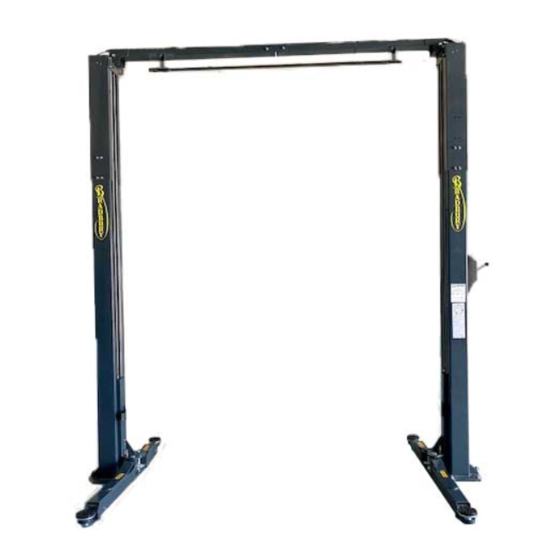
- Page 1 SB40: 2 POST HOIST Installation/Operation & Maintenance Manual SB40 Please read this manual before you get started. You must read and understand the precautions for safety purposes and any damages that may occur to your property. Updated 19/05/21...
- Page 2 NOTE TO THE USER Please read this instruction carefully for safety and proper use of the car hoist, and retain it for future reference. This Manual is for model: SB40 Design Registration V1803235 Vehicle Hoist - Model No. SB40 As for the assurance of safety in design and construction of car hoist, read this Manual first. Please make sure that this Manual is delivered to end users for their implementation of safety.
-
Page 3: Table Of Contents
TABLE OF CONTENTS Introduction Features and Characteristics Part Descriptions Description Specification Safety Danger/Warning/Caution Installation Procedures Checklist Before Installing Place of Installation-Layout Operation Check Points Before Operation Operation Operation Procedures of Each Part Maintenance Maintenance Troubleshooting Check List and Periodic Maintenance Part List... -
Page 4: Introduction
Features and Characteristics Introduction Upper limit protection bar Industrial direct drive cylinder Door protection rubber Arm lock gear ■ Upper limit protection bar ▶A limit bar prevents the vehicle from being lifted too high. This feature effectively protects taller vehicles from being damaged. - Page 5 ■ Cable adjustment ▶Correct adjustment ensures synchronization of both carriages. Cable adjustment Introduction ■ Operation of ram type cylinder Two individual cylinders ensure reliability and longevity. Unlocked Locked ■ Powerful arm lock gear ▶At the bottom position the gears are unlocked to allow arm adjustment.
-
Page 6: Part Descriptions
Part Descriptions Introduction Cross beam Power Pack Post extension Locker cover & Locker(inside) Slave post Pick-up pad Cylinder Short arm Top limit touch bar Carriage Door protection rubber pad Long arm Drive post... -
Page 7: Description
Specification SB40 MODEL CAPACITY 4,000 Kg Introduction MAX. PRESSURE 14 Mpa MAX.HEIGHT 1,895~1,940 mm MIN. HEIGHT 95~140 mm STROKE 1,800 mm LIFTING TIME Approx. 45 ~ 60 sec LOWERING TIME Approx . 35 ~ 50 sec. 3Ph, 2.2Kw, 2Poles, 415V, 50Hz POWER &... -
Page 8: Safety
Danger/Warning/Caution Rules for illustrations Make sure you follow the instructions. in the manual otherwise critical injuries can occur. Make sure you follow the instructions, otherwise critical injury or damage can occur. Make sure you follow the instructions otherwise injury or damage can occur. These are the rules for the illustrations The terms are described to enhance... - Page 9 Warning when operating Before lowering the Do not raise a vehicle Allow no unauthorized When the vehicle is using one pair of arms persons in the work hoist, check that there lifted, do not rock it as only. area. this may dislodge it. are no obstructions under the vehicle or the hoist arms...
-
Page 10: Installation Procedures
Check List Before Installing Installation site The site must be Surface load under Ambient temperature flat and horizontal. the posts must be 10℃ to 50℃. Do not operate under The floor must have minimum 25N/㎟ freezing conditions. minimum 160mm depth of reinforced concrete. -
Page 11: Place Of Installation-Layout
Place of Installation-Layout Check points before selecting the place of installation. ① Distance from wall or any fixed object ② Drive-on direction ③ Positions of power post and slave post ④ Ceiling height and height of cross member 2856 Installation 2516 3440... - Page 12 ■Setting up a post ▶Before securing with anchor bolts, ensure Vertical balance that the post is vertical in both directions. Adjusting verticality Check that the post is vertical in both directions and adjust by means of the shim plates provided. Fixing the post Fix by anchor bolts.
- Page 13 ■Cable synchronization ▶The cables ensure synchronization between the carriage on the power post and the carriage on the slave post. ① Top roller for cable. ② Synchronization cable from the opposite carriage. ③ Synchronization cable mounting bracket. ④ Bottom roller for cable. Installation Adjusting the cables Check which carriage first touches the...
- Page 14 ■Hydraulic Diagram Installation LOWERING VALVE 9/16-18 UNF...
- Page 15 ■Electrical Diagram Installation...
-
Page 16: Operation
Check Points Before Operation Before loading the hoist check the following points. ■ Test Operation ▶Operate the hoist up and down 2-3 times to check the full travel of the carriages. ■ Switch Operation ▶Check that the ascent and descent lever operate correctly. -
Page 17: Operation
Operation Prior to use Check that the carriages and arms are at lowest position by operating the lock release lever and descend lever. Prior to vehicle entry At the bottom position the arm locks are released. Swing the arms to the straightahead position as shown. -
Page 18: Operation Procedures Of Each Part
Ascent After checking that the 4 pads are correctly adjusted under the pick-up points recommended by the vehicle manufacturer and that the arm locks are engaged as previously described, press the ascent push button and raise the hoist to the required working height. - Page 19 ▶ 26K Arm 2-section telescopic arm ⓐ 920 mm ⓑ 1400 mm 3-section telescopic arm ⓐ 600 mm ⓑ 850 mm ⓒ 1075 mm 3-stage telescopic pad adjustment The height of the pad can be adjusted 3 stages as shown below. ⓐ...
-
Page 20: Maintenance
Maintenance ■ Lubrication ▶At 2-or 3-month intervals, depending on service usage. Molybdenum disulphide grease ▶Apply molybdenum disulphide grease liberally to the carriage guides and the guide runners inside the posts. Lubricating oil ▶Lubricate with oil the upper and lower cable rollers and axles. - Page 21 ■ Arms ▶Once a week check the condition of each arm by sliding each section to its fully extended position and ensure that the arm stop is working correctly. Maintenance...
- Page 22 Power pack pressure The power pack pressure is set by the factory in accordance with the lift's maximum rated capacity. The pressure regulator is sealed by the factory and should not be tampered with. Excessive adjustment can result in serious damage. If the hoist fails to raise the maximum rated load, contact your approved maintenance engineer.
-
Page 23: Troubleshooting
Troubleshooting Maintenance... -
Page 24: Check List And Periodic Maintenance
Check list and periodic maintenance Stopper screws for only when worn and deformation the sliding arms necessory only when necessory only when necessory only when necessory Maintenance... -
Page 25: Part List
PART LIST SB40 This manual was prepared in December of 2018. The Specifications/images are subject to change without prior notice, images and sketches are for illustration purposes only. - Page 26 SB40 Full Ass'y Cross beam Power Pack Post extension Locker cover & Locker(inside) Slave post Pick-up pad Short arm Cylinder Top limit touch bar Carriage Door protection rubber pad Long arm Drive post...
- Page 27 SB40 Main post Item Description Part Number Post SB40-MP-1 Extended Post SB40-MP-2 Lock Cover SB40-MP-3 Shaft SB40-MP-4 Lock Spring 1 SB40-MP-5 Lever Handle SB40-MP-6 Lever Shaft SB40-MP-7 Lock Wire Fixture SB40-MP-8 Lock Spring 2 SB40-MP-9 E-Ring SB40-MP-10 Lever Connector SB40-MP-11 Wrench Bolt SB40-MP-12 Lock Spacer...
- Page 28 SB40 Carriage & Cylinder Item Description Part Number Carriage SB40-CC-1 Carry Guide SB40-CC-2 Arm Shaft SB40-CC-3 Door Protect Rubber SB40-CC-4 Flat Washer (M8) SB40-CC-5 Wrench Bolt (M8) SB40-CC-6 Rod Bar SB40-CC-7 O-Ring SB40-CC-8 Seal Ring SB40-CC-9 Piston SB40-CC-10 Piston Ring SB40-CC-11 Wrench Bolt (M10) SB40-CC-12...
- Page 29 SB40 Slave post Item Description Part Number Carriage SB40-SP-1 Carriage Guide SB40-SP-2 Long Arm SB40-SP-3 Long Slide Arm SB40-SP-4 Slide Arm (3rd) SB40-SP-5 Slide Arm (2nd) SB40-SP-6 Short Arm SB40-SP-7 Arm Shaft SB40-SP-8 Large Arm Lock Gear SB40-SP-9 Small Arm Lock Gear SB40-SP-10 Arm Lock Spring SB40-SP-11...
- Page 30 SB40 Cross beam Item Description Part Number Upper Support Beam SB40-CB-1 Wire Roller Shaft SB40-CB-2 Snap Ring SB40-CB-3 Wire Roller SB40-MP-23 Wire Roller Spacer SB40-CB-5 Limit Switch SB40-CB-6 E-Ring SB40-CB-7 Limit Switch Fixture SB40-CB-8 Upper Limit Touch Bar SB40-CB-9 Hexa Bolt SB40-CB-10 Hexa Nut SB40-CB-11...
- Page 31 SB40 Cross beam Item Description Part Number Motor SB40-M-1 Shaft adaptor SB40-M-2 Stopper SB40-M-3 Pressure valve SB40-M-4 Manifold block SB40-M-5 Seal ring SB40-M-6 Bolt for block SB40-M-7 Pump SB40-M-8 Bolt for pump SB40-M-9 Suction pipe SB40-M-10 Filter SB40-M-11 Screw for tank SB40-M-12 Fuel tank SB40-M-13...
- Page 32 Address: 3 Graham Street Export Park South Australia 5950 +61 (08) 8234 3611 Fax: +61 (08) 8234 4322 Email: sales@molnarhoists.com.au Web: www.molnarhoists.com.au...
Need help?
Do you have a question about the MOLNAR BRADBURY SB40 and is the answer not in the manual?
Questions and answers
I need to see how the safety locker system cable and pulleys are installed