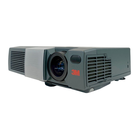
3M MP8749 Basic Technical Manual
Hide thumbs
Also See for MP8749:
- Operator's manual (43 pages) ,
- User manual (24 pages) ,
- Technical manual (12 pages)
Advertisement
Quick Links
TECHNICAL
TECHNICAL
Dimension Diagram
Signal Connector Pin Assignment
1. D-sub 15-pin Shrink Connector (RGB IN 1/RGB IN 2/RGB OUT)
Pin No
Signal
1
Video input Red
2
Video input Green
3
Video input Blue
4
-
5
Ground
6
Ground Red
7
Ground Green
8
Ground Blue
2. Mini Din 4-pin Connector (S-VIDEO)
Pin No
Color:0.286Vp-p (NTSC, burst signal),75Ω terminator
1
0.3Vp-p (PAL/SECAM, burst signal),75Ω terminator
2
Brightness:1.0Vp-p, 75Ω terminator
3
Ground
4
Ground
All manuals and user guides at all-guides.com
298
76
Pin No
9
10
Ground
11
RGB IN 1: SDA(DDC)
12
RGB IN 2: -
RGB OUT: -
13
H. sync./ Composite sync.
14
Vertical sync
Signal
94.6
54
76.5
Unit : mm
Signal
Pin No
-
RGB IN 1: SCL(DDC)
15
RGB IN 2: -
-
RGB OUT: -
Signal
#
!
"
'
&
$
%
#
"
!
TECHNICAL - 1
Advertisement

Summary of Contents for 3M MP8749
- Page 1 All manuals and user guides at all-guides.com TECHNICAL TECHNICAL Dimension Diagram 94.6 76.5 Unit : mm Signal Connector Pin Assignment 1. D-sub 15-pin Shrink Connector (RGB IN 1/RGB IN 2/RGB OUT) Pin No Signal Pin No Signal Pin No Signal Video input Red RGB IN 1: SCL(DDC) Video input Green...
-
Page 2: Example Of Computer Signal
All manuals and user guides at all-guides.com Example of computer signal Resolution fH (kHz) fV (Hz) Rating Signal mode Display mode H × × V 640 × 350 37.9 85.1 VESA VGA-1 Zoom in 640 × 400 37.9 85.1 VESA VGA-2 Zoom in 720 ×... - Page 3 All manuals and user guides at all-guides.com Initial set signals The following signals are used for the initial settings. The signal timing of some computer models may be different. In such case, refer to adjust the V.POSIT and H.POSIT of the menu. Back porch b Front porch d Back porch b...
-
Page 4: Usb Mouse
All manuals and user guides at all-guides.com Connection to the Mouse Control 1. PS/2, ADB or Serial Mouse (1) Turn off the projector and computer, and connect the two units with the appropriate cable. For PS/2 mouse control (for IBM and compatible), use the enclosed mouse cable. For others, consult your dealer. -
Page 5: Serial Mouse
All manuals and user guides at all-guides.com ADB Mouse Projector Computer ( POWER ON ) CONTROL Terminal DATA Mouse jack D-sub 15-pin shrink jack Mini DIN 4-pin ! " # % & ' ! " # Serial Mouse Projector Computer CONTROL Terminal... -
Page 6: Communications Setting
All manuals and user guides at all-guides.com RS-232C communication (1) Turn off the projector and computer power supplies and connect with the RS-232C cable. (2) Turn on the computer power supply and, after the computer has started up, turn on the projector power supply. - Page 7 All manuals and user guides at all-guides.com Requesting projector status (Get command) (1) Send the request code Header + Command data (‘02H’+‘00H’+ type (2 bytes) +‘00H’+‘00H’) from the computer to the projector. (2) The projector returns the response code ‘1DH’+ data (2 bytes) to the computer. Changing the projector settings (Set command) (1) Send the setting code Header + Command data (‘01H’+‘00H’+ type (2 bytes) + setting code (2 bytes)) from the computer to the projector.
- Page 8 All manuals and user guides at all-guides.com Command data chart Command data Names Operation type Header Action Type Setting code BE EF 06 00 3B D3 01 00 00 30 00 00 Orange BE EF 06 00 AB D2 01 00 00 30 01 00 Green...
- Page 9 All manuals and user guides at all-guides.com Command data chart Command data Names Operation type Header Action Type Setting code BE EF 06 00 7C D2 02 00 07 30 00 00 Magnify Increment BE EF 06 00 1A D2 04 00 07 30 00 00...
- Page 10 All manuals and user guides at all-guides.com Command data chart Command data Names Operation type Header Action Type Setting code Normal BE EF 06 00 46 D3 01 00 02 20 00 00 Mute Mute BE EF 06 00 D6 D2 01 00 02 20 01 00...
- Page 11 All manuals and user guides at all-guides.com Command data chart Command data Names Operation type Header Action Type Setting code BE EF 06 00 F1 72 02 00 01 22 00 00 Sharpness Increment BE EF 06 00 97 72 04 00 01 22 00 00...
- Page 12 All manuals and user guides at all-guides.com Command data chart Command data Names Operation type Header Action Type Setting code BE EF 06 00 CB D0 01 00 08 30 01 00 Sync on G BE EF 06 00 5B D1 01 00 08 30 00 00...


Need help?
Do you have a question about the MP8749 and is the answer not in the manual?
Questions and answers