
Subscribe to Our Youtube Channel
Related Manuals for Metro DataVac MB-IP


Summary of Contents for Metro DataVac MB-IP
- Page 1 MB-IP Master module for M-Bus network User’s manual +33 (0) 450 39 08 49 Metro +33 (0) 450 39 08 33 Rue de la Jonchère www.metro-fr.com F-74420 Boëge E-mail info@metro-fr.com...
-
Page 2: Table Of Contents
5.5. COMMAND TO GET INFORMATION ABOUT PROBES (METRO PROBES ONLY ON THE MB-8I MODULES) (FROM FIRMWARE VERSION 2.1) ....16 5.6. MB-IP VERSION ..................17 5.7. INPUTS/ OUTPUTS (MB-IO MODULES) ............ 17 5.8. -
Page 3: Forewords
2. FOREWORDS ONE YEAR LIMITED GUARANTEE FOR THE MB-IP MANUFACTURER'S RESPONSIBILITY SPARE PARTS AND LABOUR. The manufacturer commits himself to pay for repair or replacement costs (labour costs included) during a period of one year as from the date the guarantee came into force. - Page 4 The manufacturer is not responsible for mistakes that could be found in this handbook and also for direct or indirect damage resulting from the equipment, its performances and the use of this product. CLEANING Use a soft cotton cloth slightly soaked with an ethyl alcohol based product. DO NOT USE the following products: acetone, benzene, toluene and halogens hydrocarbons.
-
Page 5: Introduction
3. INTRODUCTION 3.1. PRODUCT PRESENTATION The MB-IP module allows to connect the entire range of M-Bus modules (except the MB-BT – Bluetooth) on a PC or a PLC with USB or Ethernet through and ASCII protocol or with MODBUS-TCP. Up to 254 inputs can be connected. -
Page 6: Dimensions And Installation
3.2.2. Dimensions and installation The M-Bus modules are made on a robust aluminium profile. All the M-Bus modules are designed and must be installed on a standard DIN rail (7.5*35) in order to ensure a correct fixation. Version 1.0... -
Page 7: Contains Of The Packaging
3.2.1. Contains of the packaging The MB-IP package contains : - 1 MB-IP module - 1 USB cable - 1 transformer + 1 power supply cable - 1 Mini-CD including USB driver and this user manual... -
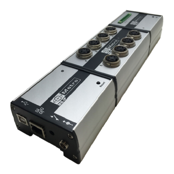
Page 8: Connectors
4. CONNECTORS USB Full-Speed with ASCII protocol (Creates a virtual COM PORT) Ethernet with ASCII or modbus TCP. RJ45 connector. Footswitch input Power supply connector 12-30 VDC Reset button Version 1.0... -
Page 9: The Usb Full-Speed Connector
4.1. THE USB FULL-Speed CONNECTOR This section is useful to setup the IP address of the module, or if you intend to use the MB-IP with the USB connection. Connecting the MB-IP on the computer with USB will create a virtual COM Port. -
Page 10: Communication - Ascii Protocol
Before reading the probes, it is necessary to identify the connected modules on the MB-IP. This has to be done only the first time. Up to 254 input can be connected. The address of the input will thus be from 00 to ... - Page 11 o Answer : XXXXXXXXXX<$0D> when the module has been correctly identified (example : 9#I816102422<CR>). The value corresponds to the unique identification number of the module. Example : identify a MB-8I (8 inductive probes), a MB-4C module (4 Sylvac capacitive probes), and a MB-IO module (8 inputs/outputs) : 00 to 07 08 to 0B STEP 1 –...
- Page 12 List of identified modules o Command : @ID? <$0D> o Answer : @NN=XXXXXXXXXX<$0D> @NN=XXXXXXXXXX<$0D> @NN=XXXXXXXXXX<$0D><$0A> Where NN=address of the first channel of the module Where XXXXXXXXXX = ID number of the module If no module is identified, the answer will be : <$0D><$0A> Example : make the list of the modules identified on the last example : 00 to 07 08 to 0B...
- Page 13 Erase 1 module : o Command : @CL=XX<$D> Where XX = address of the first channel of the module to be removed. Example : erase the MB-4C module identified on the last example : 00 to 07 08 to 0B o Command : @CL=08<$D>...
-
Page 14: Commands For Reading The Probes
5.3. Commands for reading the probes For asking the value of a probe, the computer or PLC must send a 3 characters string : o Command : NN<$0D> with NN = address of the probe o Answer : +/-000.0000 <$0D> (position in mm) ... -
Page 15: Commands For Reading Multiple Probes (From Firmware Version 2.1)
5.4. Commands for reading multiple probes (from firmware version 2.1) For asking the value of several probes, the computer or PLC must send a 6 characters string : o Command : SS :EE<$0D> with SS = address of the first probe and EE the address of the last probe o Answer : +/-000.0000;+/-000.0000;…... -
Page 16: Command To Get Information About Probes (Metro Probes Only On The Mb-8I Modules) (From Firmware Version 2.1)
Example : read the probes n°1 to 5 connected on the MB-8I (8 inductive probes previously identified on the last example : The probe°1 of the first module is at the address 00 The probe°5 of the first module is at the address 04 Command : 00:04<$0D>... -
Page 17: Mb-Ip Version
Answer : XXX<$0D> (XXX is the version number) 5.7. Inputs/ Outputs (MB-IO modules) It is possible to connect MB-IO modules on the MB-IP. MB-IO modules are fitted with 8 optocoupled inputs/outputs. The 8 outputs are similar to the « open collector PNP » type. They can be used with an external power supply 12 to 30 VDC maximum. - Page 18 Output PLC output 0V of the PLC MB-IO module + 24V + 24V + 24 V from the PLC Input Output to PLC 0V of the PLC MB-IO module Examples of connection between a PLC and a MB-IP Version 1.0...
- Page 19 Outputs Activate 1 or several outputs : Command : OXX=YY<$0D> Where XX = address of the MB-IO module and YY the status of the outputs in Hexadecimal Example : Activate the output 8, 7 and 2 of the MB-IO module, previsouly identified at the adress 0C number Command : O0C=C2<$0D>...
-
Page 20: Resolution Of A Module For Ttl Probes (Module Mb-2T)
5.7.1. Resolution of a module for TTL probes (module MB-2T) If you use the MB-2T module for TTL probes, you will need to send a command for setting the resolution of each input of the module, depending on the probe you have connected. -
Page 21: Definition Of The Temperature Input On The Mb-Tp Modules (From Firmware Version 2.1)
Reading the MIN master value Command @AGLnn?<$0D>, where nn=address of the module Answer 99850<$0D> (according to previous example) Reading the MAX master value Command @AGHnn?<$0D>, where nn=address of the module Answer 100150<$0D> (according to previous example) 5.7.5. Definition of the temperature input on the MB-TP modules (from firmware version 2.1) The MB-TP module has 2 temperature sensors connectors (for PT100 sensors or Type K thermocouples) but 1 sensor can be used:... -
Page 22: Modbus Tcp Communication Protocol
6. MODBUS TCP COMMUNICATION PROTOCOL This protocol allows to connect the MB-IP on a PLC compatible with the MODBUS TCP. This protocol allows to control all the functionalities of the MB-IP through several registers. Up to 256 registers can be read by data frame.
Need help?
Do you have a question about the MB-IP and is the answer not in the manual?
Questions and answers