
Subscribe to Our Youtube Channel
Related Manuals for AS RTP9007S


Summary of Contents for AS RTP9007S
- Page 1 2021.01.25 RTP9007S TESTER FOR VOLTAGE REGULATORS OF ALTERNATORS OPERATION MANUAL ON DIAGNOSTICS OF ALTERNATORS AND VOLTAGE REGULATORS...
-
Page 3: Table Of Contents
English Operation manual CONTENTS INTRODUCTION ..............................1 TESTER DESCRIPTION ............................. 2 TESTER MENU ..............................2.1. Test modes menu..........................3 INTENDED USAGE ............................3.1 Safety regulations ..........................4 DIAGNOSTICS OF VOLTAGE REGULATORS ....................4.1 Voltage regulator connection ......................4.2 Diagnostics of voltage regulators of Lamp type ................. 4.3 Diagnostics of voltage regulators of RLO, RVC, C KOREA types .......... -
Page 4: Introduction
RTP9007S INTRODUCTION The actual instruction describes the technique of voltage regulator diagnostics (hereinafter “the voltage regulator”) with tester RTP9007S (hereinafter “the tester”) to detect faults in alternator and voltage regulator performance. WARNING! The actual instruction does not provide a description of all the diagnostic aspects. -
Page 5: Tester Description
There is a USB Type-C port in the bottom part of the tester, through which the power is supplied to the tester during the diagnostics of voltage regulators. The USB port serves as well for connection of the tester to a computer either for software updating or for data copying (Fig.3). - Page 6 English tester RTP9007S Figure 3 - USB port, Type-C A diagnostic cable for voltage regulators (Fig.4) and adapter cables (Fig.5) for easy connection to the voltage regulator output terminals are included in the tester set. Figure 4 – Diagnostic cable for voltage regulators MS-33502 Figure 5 –...
- Page 7 English Operation manual The diagnostic cable for voltage regulators (Fig.4) has the following color markings (Table 1): Red cable with a clip – B+ – voltage regulator terminal B+ (terminal 30); • Black cable with a clip – B- – voltage regulator terminal B- (GND, terminal 31); •...
- Page 8 English tester RTP9007S Table 1 – Color markings of cable MS-33502 Tester output Clip/Terminal terminal F1, F2 ST1, ST2...
- Page 9 English Operation manual The equipment set includes a cable for alternator diagnostics (Fig.6). Figure 6. MS-33501 – Diagnostic cable for alternators The diagnostic cable (Fig.6) has the following color markings: Red clip, big – „В+”; • Black clip, big – „В-”; •...
-
Page 10: Tester Menu
English tester RTP9007S 2 MENU TESTERA The tester main menu (Fig. 7) contains: Figure 7. Tester main menu 1 – Button to enter a search menu of the voltage regulator database; 2 – Button to enter the menu for selection of the tested voltage regulator type;... - Page 11 English Operation manual The tester is supplied with an integrated database of voltage regulators along with their connection diagrams. Press to enter the database search menu (Fig.7, n.1). Figure 8 - Database search menu Figure 9 - Menu for selection of the tested voltage regulator type...
-
Page 12: Test Modes Menu
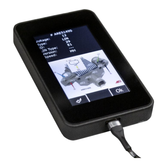
English tester RTP9007S Press the button with the required type of the voltage regulator to enter the alternator/voltage regulator test mode. Press to return to the main menu. 2.1 Test modes menu Upon entering the test mode for voltage regulators, the following information will appear on the screen (Fig.10):... - Page 13 „Type” – voltage regulator type. The type codes of voltage regulators operating under LIN protocol are as follows: A1, A2, A3, A4, B1, B2, B3, B4, C3, D1, D2, E1; „Duty” - PWM signal duty cycle (the proportion of the rotor winding “on” time);...
- Page 14 English tester RTP9007S „Version LIN” – indicator of voltage regulator protocol version (LIN1 or LIN2); „Errors” - indicator of errors transmitted by the voltage regulator to the engine control unit. Types of potential errors: • E – electrical error; • M – mechanical error;...
- Page 15 English Operation manual alternator voltage regulator Figure 13 - Diagnostic screen for alternators/voltage regulators of C JAPAN type alternator voltage regulator Figure 14 - Diagnostic screen for alternators/voltage regulators (12/24V) of Lamp type...
-
Page 16: Intended Usage
(over 75%). Do not turn on the tester immediately after moving it from a cold room (or from outdoors) into a warm one as its components may be covered with a condensate. Keep it off at room temperature for at least 30 min. -
Page 17: Safety Regulations
3) Assessment of the control lamp operability: when speed is about 0 rpm, the battery indicator must light up (red). As the speed increases up to 800-1200 rpm, the indicator must go out. 4) Assessment of the „S” terminal operability;... - Page 18 RTP9007S Figure 16 - Voltage regulator search against the database and search results Connect the diagnostic cable to the voltage regulator as shown on the diagram. WARNING! To avoid damage (failure) to the voltage regulator, extra care should be taken when connecting the cable clips to the contacts in the terminals.
- Page 19 Identify the type of the voltage regulator by the terminal contacts shown in Fig.18 and use information set out in Appendices 1, 2 of the actual Instruction. Shown here are terminals DFM and L(RVC) (can also be marked as L(PWM)). By terminal L (RVC) we identify this voltage regulator as RVC type.
- Page 20 RTP9007S Figure 19 - Diagram of voltage regulator ARE1054 connection to the tester Figure 20 shows a diagram of voltage regulator ARE6076 connection as an example. Figure 20 - Voltage regulator ARE6076 The voltage regulator type is identified by the terminal contacts and based on the information set out in Appendices 1, 2.
- Page 21 English Operation manual Table 3 – Connection of voltage regulator ARE6076 to the tester Voltage regulator Tester output Color marking of terminal terminal cable grey orange FR(M) white green green blue black Figure 21 - Diagram of voltage regulator ARE1054 connection to the tester Connection of voltage regulator ARE6076 has a specific feature.
- Page 22 English tester RTP9007S Figure 22 shows the connection diagram of voltage regulator ARE6149P as an example. Figure 22. Voltage regulator ARE6149P The voltage regulator type is identified by terminal contacts and based on the information set out in Appendices 1, 2. There is only one terminal – LIN, which identifies this voltage regulator as COM type.
-
Page 23: Diagnostics Of Voltage Regulators Of Lamp Type
Connection of voltage regulator ARE6149P has a specific feature. We connect cable F1 to the only terminal – F. As the actual voltage regulator is B-circuit type, the other cable (F2) must be connected to terminal B-. Consequently, one of the brushes is permanently connected to B- of the alternator, while the excitation winding is controlled through terminal B+. -
Page 24: Diagnostics Of Voltage Regulators Of Rlo, Rvc, C Korea Types
English tester RTP9007S 6. Failure to perform as described in sub-items 3-5 signals the voltage regulator malfunction. 7. Press BACK to exit the test mode. Disconnect the clips form the voltage regulator. 4.3 Diagnostics of voltage regulators of RLO, RVC, and C KOREA types 1. -
Page 25: Diagnostics Of Voltage Regulators Of C Japan Type
7. Press BACK to exit the test mode. Disconnect the clips from the voltage regulator. 8. Failure to perform as described in sub-items 3-5 signals the voltage regulator malfunction. 4.5 Diagnostics of voltage regulators of SIG and P/D types 1. -
Page 26: Diagnostics Of Alternators
2. Enter the voltage regulator type selection mode, select the nominal voltage (12 or 24 volts) and activate the test mode for COM voltage regulators. 3. Wait for the tester to read-out data. As soon as the values are displayed in ID, Version LIN, and Type boxes we can proceed to testing. - Page 27 * This does not apply to the alternators of SIG and P/D types. 3.2 If this is the alternator with COM terminal, wait for the tester to readout the data. As soon as the values appear in ID, Version LIN, and Type boxes, proceed to testing.
- Page 28 (Field Report) Output for alternator load control by an engine control unit Digital Field Monitor Monitor (Load Indicator) Same as FR, but with universal signal (Drive) Input of voltage regulator control with terminal P-D of Mitsubishi (Mazda) and Hitachi (KiaSephia1997-2000) alternators...
- Page 29 (Signal) Input of code voltage installation (Digital) Input of code voltage installation on Ford, same as SIG (Regulator control), same as SIG (Regulated Voltage Control) Similar to SIG but L(RVC) voltage change ranges from 11V to 15.5V. Control L(PWM) signal is sent to L terminal.
- Page 30 English tester RTP9007S Voltage Indicial Output Functional purpose regulator notation terminal type (Wave) Output of one of alternator stator windings for connection of a tachometer in diesel engine cars (Null) Output of average stator winding point. Usually used to control operability indicator lamp...
-
Page 31: Appendix 2
English Operation manual APPENDIX 2. Connection terminals of different voltage regulator types... - Page 32 English tester RTP9007S...
- Page 33 English Operation manual...
- Page 34 English tester RTP9007S APPENDIX 3. Connection of voltage regulators to the tester...
- Page 35 English Operation manual...
- Page 36 English tester RTP9007S...
- Page 37 English Operation manual...
- Page 38 English tester RTP9007S...
- Page 39 English Operation manual...
- Page 40 English tester RTP9007S...
- Page 41 English Operation manual...
- Page 44 Produced by 18 Biolohichna St. 61030 Kharkiv, Ukraine +38 (057) 728 0171 Technical Support: support@servicems.eu General Enquiries: sales@servicems.eu Skype: MSG Equipment servicems.eu...
Need help?
Do you have a question about the RTP9007S and is the answer not in the manual?
Questions and answers