Advertisement
Quick Links
Advertisement

Related Manuals for Titan TLEBSK4X6


Summary of Contents for Titan TLEBSK4X6
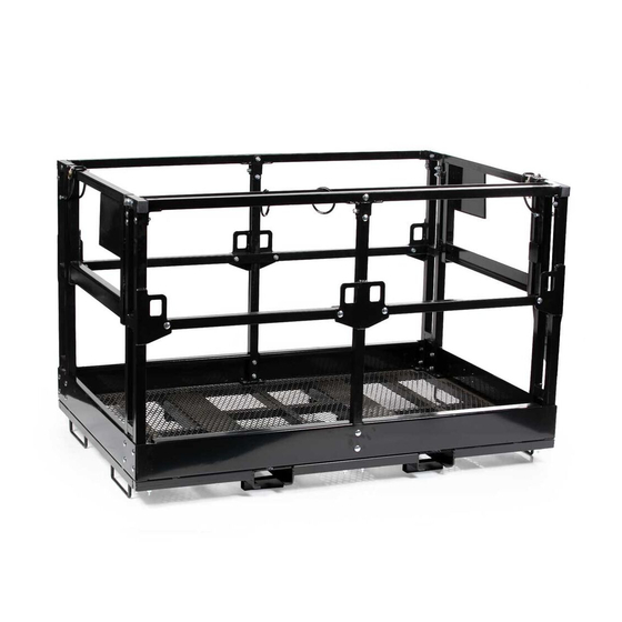
- Page 1 TELEHANDLER SAFETY MANBASKET TLEBSK4X6, TLEBSK4X8, TLEBSK4X98 190502,191503,191504 Operator’s Manual Read the Operator’s Manual entirely. When you see this symbol, the subsequent instructions and warnings are serious follow without exception. Your life and the lives of others depend on it!
- Page 2 INTRODUCTION THESE ARE STANDARD PRACTICES THAT MAY NOT APPLY TO THE PRODUCTS DESCRIBED IN THIS MANUAL. PRECAUTIONS This manual is made at the time of manufacturing of the work platform that does not • include any subsequent modifications made afterward. This manual is intended to provide information to operators and owners to operate the •...
-
Page 3: Special Notes
ASSEMBLY INSTRUCTIONS SPECIAL NOTES: Build on flat and level ground • Avoid tightening bolts down completely until the rack is fully assembled • • Reference positions: left/right/front/back are from forklift cab viewing the work platform STEP 1: INSTALLING CORNER FRAMES DESCRIPTION DESCRIPTION BASE ASSY... - Page 4 STEP 1: INSTALLING CORNER FRAMES 1. Rest CORNER FRAME-1 (4) on the left/front corner of the BASE ASSY (1) and align bolt holes. Insert CARRIAGE BOLT M10x60 (20) through the holes from the side and place FLAT WASHER M10 (21), SPRING WASHER M10 (22) and HEX NUT M10 (23) onto the end of the bolt.
-
Page 5: Step 2: Installing Guard Rails
STEP 2: INSTALLING GUARD RAILS DESCRIPTION DESCRIPTION BASE ASSY (17) CARRIAGE BOLT M10x70 TOP GUARD RAIL (18) CARRIAGE BOLT M10x80 UPRIGHT POST ASSY (19) CARRIAGE BOLT M10x65 CORNER FRAME-1 (20) CARRIAGE BOLT M10x60 CORNER FRAME-2 (21) FLAT WASHER M10 RAIL MOUNTING PLATE – 1 (22) SPRING WASHER M10 (14) - Page 6 STEP 2: INSTALLING GUARD RAILS 1. Rest UPRIGHT POST ASSY (3) on the middle of the BASE ASSY (1) and align bolt holes. Insert CARRIAGE BOLT M10x80 (18) through the bolt holes from the top and place FLAT WASHER M10 (21), SPRING WASHER M10 (22) and HEX NUT M10 (23) onto the end of the bolt. Then insert CARRIAGE BOLT M10x60 (20) through the holes from the side and place FLAT WASHER M10 (21), SPRING WASHER M10 (22) and HEX NUT M10 (23) onto the end of the bolt.
- Page 7 STEP 3: INSTALLING GATES AND FINAL TOUCH DESCRIPTION DESCRIPTION BASE ASSY (20) CARRIAGE BOLT M10x60 CORNER FRAME-1 (21) FLAT WASHER M10 CORNER FRAME-2 (22) SPRING WASHER M10 GATE FRAME (23) HEX NUT M10 LOCK PIN ASSY – FORK (8) (24) FLAT WASHER M16 GATE SWING STOPPER (25)
- Page 8 STEP 3: INSTALLING GATES AND FINAL TOUCH 1. Attach GATE SWING STOPPER (9) onto CORNER FRAME-1 (4) or CORNER FRAME-2 (5) using CARRIAGE BOLT M10x60 (20), FLAT WASHER M10 (21), SPRING WASHER M10 (22), and HEX NUT M10 (23). The order of assembly is to push CARRIAGE BOLT M10x60 (20) through these parts, and then FLAT WASHER M10 (21), SPRING WASHER M10 (22), and HEX NUT M10 (23) onto the end of the bolt.
-
Page 9: Inspections Before Use
OPERATION INSTRUCTIONS Work platform operator must acquire appropriate qualification or license to work in • elevated height according to requirements of local regulations. Forklift or telehandler operator must acquire appropriate qualification or license and • fully trained to maneuver elevated loads. Operator must be mentally sound and not being affected by drugs or alcoholic drinks •... - Page 10 Move forklift to designated lifting position and make sure that the forklift or telehandler • is in parking brake (engage outrigger if available) before elevating personnel. Platform personnel should enter work platform on ground. After entering platform, • engage the gate latch and safety pin and make sure the gates are locked securely. Put on safety lanyard or harness and lock it on the harness ring before signaling forklift operator to elevate.
- Page 11 AFTER USE AND MAINTENANCE Only qualified peronnel should make repairs to the work platform. After completing • repair and maintenance, check if the work platform is in good conditions. Inspection and maintenance can only be conducted with engine turned off and auxiliary •...
- Page 12 SPECIFICATIONS TLEBS 4X6 TLEBSK4X8 TLEBSK4X98 OVERALL DIMENSIONS 72”X 54.3” X 46.7” 96”X 54.3” X 46.7” 116”X 54.3” X 46.7” (L X W X H) PRODUCT WEIGHT 485 LB. 542 LB. 628 LB. LOAD CAPACITY 1700 LB. FORK CHANNEL 6.25” X 2.5” HANDRAIL HEIGHT 42”...
- Page 13 PARTS DIAGRAM / EXPLODED VIEW...
- Page 14 PARTS DIAGRAM / EXPLODED VIEW DESCRIPTION BASE ASSY (16) TUBE END PLASTIC CAP DOME HEAD CARRIAGE TOP GUARD RAIL (17) BOLT M10 70 DOME HEAD CARRIAGE UPRIGHT POST ASSY (18) BOLT M10x80 DOME HEAD CARRIAGE CORNER FRAME-1 (19) BOLT M10x65 DOME HEAD CARRIAGE CORNER FRAME-2 (20)
- Page 15 Titan, its insurers, employees, officers, directors, associates, and agents from any and all claims, demands, damages, rights of action, or causes of action, present or future, whether the same be known or unknown, anticipated, or unanticipated, resulting from or arising out of the use of said equipment.
- Page 16 NEED HELP? CONTACT US FIRST. 1-800-605-7595 info@palletworks.com www.palletforks.com © 2021 Titan Brands...
Need help?
Do you have a question about the TLEBSK4X6 and is the answer not in the manual?
Questions and answers