
Related Manuals for Powell EcoVisor 01.41B.48080

Summary of Contents for Powell EcoVisor 01.41B.48080
- Page 1 DRAFT Powered by Safety ® Instruction Bulletin - 01.4IB.48080 EcoVisor™ Environmental Monitoring System...
- Page 2 EcoVisor™ 01.4IB.48080 Contact Information Powell Electrical Systems, Inc. powellind.com info@powellind.com Service Division 7232 Airport Blvd. Houston, Texas 77061 Tel: 1.800.480.7273 Powered by Safety ®...
- Page 3 01.4IB.48080 Signal Words Qualified Person As stated in ANSI Z535.4-2007, the signal word is For the purposes of this manual, a qualified a word that calls attention to the safety sign and person, as stated in NFPA 70E®, is one who has designates a degree or level of hazard seriousness.
- Page 4 EcoVisor™ 01.4IB.48080 This page is left blank intentionally. Powered by Safety ®...
-
Page 5: Table Of Contents
01.4IB.48080 Contents Ch 1 General Information ....................1 A. S ................................2 cope B. p ................................2 urpoSe c. A ..........................2 pprovAl And ertificAtionS d. i .....................2 nStruction ulletinS vAilABle lectronicAlly e. A ............................2 SSociAted ulletinS Ch 2 Safety ........................3 A. S ............................3 ondition B. - Page 6 EcoVisor™ 01.4IB.48080 Contents Ch 6 Maintenance ......................19 A. H ........................19 uMidity And eMperAture enSor 1) Expected Life Span .................................19 2) Sensor Replacement ................................19 B. d ........................20 enSor leAninG And eroinG 1) Cleaning ....................................20 2) Zeroing ......................................21 c. f ..............................
- Page 7 Clean Window ....................21 Figure 22 Precision Hex Screwdriver 2mm ..............21 Figure 23 Factory Reset ....................22 Figure 24 Start Powell Bootloader Utility ..............23 Figure 25 Select Hex File ....................23 Figure 26 Select Com Port .....................23 Figure 27 Firmware Programming Sequence ...............23 Figure 28 Bootloader Errors ..................24...
- Page 8 EcoVisor™ 01.4IB.48080 Tables Table A System Sensor Specifications ................8 Table B EcoVisor™ LED Indicators ..................11 Table C Part Numbers for RJ12 Cables ................13 Table D Default Communication Settings ................14 Table E EcoVisor™ Holding Registers ................14 Table F EcoVisor™ Input Registers ..................15 Table G Factory Reset Defaults ..................21 Table H Troubleshooting ....................25 Powered by Safety...
- Page 9 01.4IB.48080 This page is left blank intentionally. Powered by Safety ®...
-
Page 10: Ch 1 General Information
The information in this instruction bulletin is not intended to explain all details or variations of the Powell equipment, nor to provide for every possible contingency or hazard to be met in connection with installation, testing, operation, and maintenance of the equipment. For additional information and instructions for particular problems, which are not presented sufficiently for the user’s purposes, contact Powell at 1.800.480.7273. -
Page 11: S Cope
EcoVisor environmental monitoring system 3. Information for ordering renewal parts For more information visit powellind.com. 4. Illustrations, photographs, and description To contact the Powell Service Division call of the EcoVisor environmental monitoring 1.800.480.7273 or email system info@powellservice.com. -
Page 12: Ch 2 Safety
01.4IB.48080 Ch 2 Safety N Exception No. 1: An adequately rated permanently mounted test device shall be A. S permitted to be used to verify the absence of ondition voltage of the conductors or circuit parts at The information in Section A is quoted from the work location, provided it meets the all NFPA 70E 2018 - Article 120, 120.5 Establishing an following requirements: (1) It is permanently... -
Page 13: S Afety G Uidelines
EcoVisor™ 01.4IB.48080 B. S 8. Where the possibility of induced voltages Afety uidelineS or stored electrical energy exists, ground Study this instruction bulletin and all other the phase conductors or circuit parts associated documentation before installing the before touching them. Where it could be EcoVisor™... -
Page 14: S Pecific
If for any reason an interlock does not function as described, do not make any adjustments, modification, or deform the parts. DO NOT FORCE THE PARTS INTO POSITION. CONTACT POWELL FOR INSTRUCTIONS. e. S Afety ABelS... -
Page 15: Ch 3 Equipment Description
NOTICE Figure 1 EcoVisor™ Environmental Monitor Powell is committed to continuous product improvement. It is possible that improvements occurred between revisions to this document and therefore, may not be described in these instructions. -
Page 16: Figure 2 Ecovisor™ Connected Via Britespot® Plus
01.4IB.48080 Figure 2 EcoVisor™ Connected via BriteSpot® Plus ETHERNET OR RS-485 RS-485 -OR- BRITESPOT® PLUS ECOVISOR™ Alternatively, the EcoVisor may be incorporated as a client device into an existing RS-485 network and its data collected by a connected HMI or other control system as shown in Figure Figure 3 EcoVisor™... -
Page 17: S Pecifications
EcoVisor™ 01.4IB.48080 c. S pecificAtionS Table A System Sensor Specifications Parameter Detection Accuracy Resolution Refresh Response Range Rate Time* Sensors Dust 0-1 mm ±0.05 mm 0.01 mm 50 ms Figure 4 Relative Humidity Relative Humidity 20% to 95% RH 0.1% RH Sensor Accuracy Temperature -40°C to +85°C... -
Page 18: Figure 4 Relative Humidity Sensor Accuracy
01.4IB.48080 Figure 4 Relative Humidity Sensor Accuracy Relative Humidity Accuracy 20 25 30 35 40 45 50 55 60 65 70 75 80 85 90 95 % Relative Humidity Powered by Safety ® Equipment Description... -
Page 19: D Escription
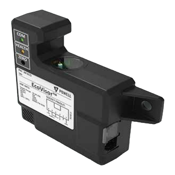
EcoVisor™ 01.4IB.48080 d. H ArdWAre eScription Refer to Figure 5 for the location of the EcoVisor™ physical features. Figure 5 EcoVisor™ Overall Views a. Optical Dust Sensing Window b. Communication Status Indicator LED c. Power and Environmental Condition Indicator LED d. -
Page 20: Table B Ecovisor™ Led Indicators
01.4IB.48080 Table B EcoVisor™ LED Indicators Indicator Color Description Solid GREEN Low dust level Solid AMBER Moderate dust level Health Solid RED Extreme dust level Flashing GREEN for 3 seconds Dust zero point has been set Flickering GREEN (may appear dim during intermittent Traffic on the RS-485 network communication) No traffic on the RS-485 network... -
Page 21: Ch 4 Installation
The EcoVisor has two 6 conductor modular jacks which are connected internally to provide easy daisy chaining of several devices. Pre-terminated cables are available from Powell, refer to Table C, Part Numbers for RJ12 Cables. The RJ12 breakout adapter listed in... -
Page 22: Figure 7 Ecovisor™ Pinout
01.4IB.48080 Figure 7 EcoVisor™ Pinout E c o V i s o r ™ L O O K I N G I N T O C O N N E C T O R 1 - G N D 2 - N C 3 - N C 4 - R S - 4 8 5 B 5 - R S - 4 8 5 A... -
Page 23: Ch 5 Operation
EcoVisor™ 01.4IB.48080 Ch 5 Operation A. S tAndAlone This section describes how to communicate with the EcoVisor™ using the Modbus RTU protocol. Should it be necessary to reset the communication settings to default, refer to Ch 6 Maintenance, C. Factory Reset. -
Page 24: Table F Ecovisor™ Input Registers
01.4IB.48080 Table F EcoVisor™ Input Registers Register Range, Modbus Description Default UOM: Register Interpretations Name format: Offset General Parameters - 300001 to 300009 PCB Part HW P/N 10230 0-65535 30001 Number Firmware FW Rev 0-65535 30002 Revision Manufacturing Day of 1-31 30003 Manufacture... -
Page 25: O Peration With B Rite S Pot ® P Lus
EcoVisor™ 01.4IB.48080 B. o ® p Figure 9 Connection Diagram perAtion WitH rite 1) Electrical Connection E c o V i s o r ™ L O O K I N G I N T O C O N N E C T O R 1 - G N D For connection to the BriteSpot Plus, a 2 - N C... -
Page 26: Changing The Slave Id
01.4IB.48080 2) Changing the Slave ID Figure 12 Modbus Poll Read/Write Definition a. Double click on the value for the slave ID in the Modbus Poll window for the holding register, the following dialogue will appear shown in Figure Figure 11 Slave ID Change d. -
Page 27: Changing The Baud Rate
EcoVisor™ 01.4IB.48080 Figure 14 Modbus Poll Connection Setup 3) Changing the Baud Rate a. Double click on the value for the baud rate in the Modbus Poll window for the holding register. The following dialogue will appear shown in Figure Figure 13 Baud Rate Change e. -
Page 28: Ch 6 Maintenance
As such, it may become necessary to replace the sensor should spurious readings occur. 2) Sensor Replacement a. Required Tools EcoVisor replacement humidity and temperature sensor: Powell part number AP.ECO-RH a. Insert Screwdriver Figure 15 EcoVisor Replacement Sensor b. Slide Sensor out of Module... -
Page 29: D Ust S Ensor C Leaning And Z Eroing
EcoVisor™ 01.4IB.48080 Figure 20 Sensor Inserted c. Sensor Installation Disconnect the power to the Ecovisor™. ii. Slide sensor module in as shown in Figure 19. DO NOT FORCE. Figure 19 Inserting Sensor Module a. Retaining Clip d. Apply power to the EcoVisor. B. -
Page 30: Zeroing
01.4IB.48080 Figure 21 Clean Window c. f Actory eSet In certain circumstances it may be necessary to restore the EcoVisor™ to the default settings. This will return the Modbus settings to the values shown below, as well as zeroing the dust level. -
Page 31: Factory Reset Procedure
Powell Service at bootloader mode 1.800.480.7273 or email info@powellind.com. e. Start the Powell Bootloader Utility. 1) Required Tools 1. The most current version of the Powell Bootloader Utility: • 60092-sw-bootloader-rev-x.xx.xx. x64 (64 bit) •... -
Page 32: Figure 24 Start Powell Bootloader Utility
01.4IB.48080 Figure 24 Start Powell Bootloader Utility Figure 26 Select Com Port h. Click “Program”, the device will be programmed with the selected firmware. Figure 27 Firmware Programming Sequence f. Browse to the location of the firmware hex file and select it. -
Page 33: Figure 28 Bootloader Errors
EcoVisor™ 01.4IB.48080 Once the programming completes successfully, the software displays “Done” and the unit will reboot. At this point, the USB cable may be disconnected from the unit. If there has been a communication error, or the power has been interrupted during boot loading the following errors will appear. -
Page 34: Ch 7 Troubleshooting
01.4IB.48080 Ch 7 Troubleshooting Table H Troubleshooting Symptom Likely Cause(s) Possible Solutions Verify connections to unit, see EcoVisor™ LED’s not illuminated Power connected incorrectly Ch 4 Installation, B. Electrical Connection Upload most current firmware, see COM LED flashing amber, unit not Firmware corrupt or no firmware Ch 6 Maintenance, D. -
Page 35: Appendix A Mechanical Drawings - Mounting Pattern
EcoVisor™ 01.4IB.48080 Appendix A Mechanical Drawings - Mounting Pattern Powered by Safety ® Appendix A... - Page 36 01.4IB.48080 EcoVisor™ Environmental Monitoring System June 2020 Powered by Safety ® Powell Electrical Systems, Inc. Tel: 1.800.480.7273 Service Division - Houston powellind.com 7232 Airport Blvd. • Houston, TX • 77061 info@powellind.com ©2006 Powell Industries, Inc. • All rights reserved.
Need help?
Do you have a question about the EcoVisor 01.41B.48080 and is the answer not in the manual?
Questions and answers