Sign In
Upload
Manuals
Brands
Powell Manuals
Measuring Instruments
EcoVisor 01.41B.48080
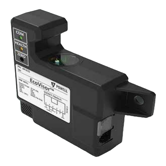
Powell EcoVisor 01.41B.48080 Manuals
Manuals and User Guides for Powell EcoVisor 01.41B.48080. We have
1
Powell EcoVisor 01.41B.48080 manual available for free PDF download: Instruction Bulletin
Powell EcoVisor 01.41B.48080 Instruction Bulletin (36 pages)
Environmental Monitoring System
Brand:
Powell
| Category:
Measuring Instruments
| Size: 1 MB
Table of Contents
Table of Contents
5
Ch 1 General Information
10
S Cope
11
P Urpose
11
A Pproval and Ertifications
11
I Nstruction B Ulletins a Vailable E Lectronically
11
Associated B Ulletins
11
Ch 2 Safety
12
S Afe W Ork C Ondition
12
S Afety G Uidelines
13
G Eneral
13
S Pecific
14
S Afety Abels
14
Ch 3 Equipment Description
15
G Eneral
15
D Evice O Verview
15
Figure 1 Ecovisor™ Environmental Monitor
15
Figure 2 Ecovisor™ Connected Via Britespot® Plus
16
Figure 3 Ecovisor™ Connected Directly to RS-485 Network
16
S Pecifications
17
Table a System Sensor Specifications
17
Figure 4 Relative Humidity Sensor Accuracy
18
D Escription
19
Figure 5 Ecovisor™ Overall Views
19
Table B Ecovisor™ LED Indicators
20
Ch 4 Installation
21
M Ounting
21
E Lectrical C Onnection
21
Figure 6 Ecovisor™ Mounting Pattern
21
Figure 7 Ecovisor™ Pinout
22
Figure 8 RJ12 Breakout Adapter
22
Table C Part Numbers for RJ12 Cables
22
Table D Default Communication Settings
23
Table E Ecovisor™ Holding Registers
23
Ch 5 Operation
23
S Tandalone
23
Table F Ecovisor™ Input Registers
24
O Peration with B Rite S Pot ® P Lus
25
Electrical Connection
25
Setup
25
Q Uick S Tart G Uide
25
Establishing Connection to the Ecovisor
25
Figure 9 Connection Diagram
25
Figure 10 Initial Connection Setup
25
Changing the Slave ID
26
Figure 11 Slave ID Change
26
Figure 12 Modbus Poll Read/Write Definition
26
Changing the Baud Rate
27
Figure 13 Baud Rate Change
27
Figure 14 Modbus Poll Connection Setup
27
Ch 6 Maintenance
28
H Umidity and T Emperature S Ensor
28
Expected Life Span
28
Sensor Replacement
28
Figure 15 Ecovisor Replacement Sensor
28
Figure 16 Slotted Screwdriver
28
Figure 17 Remove Sensor Module
28
Figure 18 Sensor Module Removed
28
D Ust S Ensor C Leaning and Z Eroing
29
Cleaning
29
Figure 19 Inserting Sensor Module
29
Figure 20 Sensor Inserted
29
Zeroing
30
Actory R Eset
30
Required Tools
30
Figure 21 Clean Window
30
Figure 22 Precision Hex Screwdriver 2Mm
30
Table G Factory Reset Defaults
30
Factory Reset Procedure
31
F Irmware U Pdate
31
Required Tools
31
Firmware Upload Procedure
31
Figure 23 Factory Reset
31
Figure 24 Start Powell Bootloader Utility
32
Figure 25 Select Hex File
32
Figure 26 Select Com Port
32
Figure 27 Firmware Programming Sequence
32
Figure 28 Bootloader Errors
33
Table H Troubleshooting
34
Ch 7 Troubleshooting
34
Appendix A Mechanical Drawings - Mounting Pattern
35
Advertisement
Advertisement
Related Products
Powell 05PV36ARMX-4
Powell 05PV50ARMX-4
Powell 05PV63ARMX-4
Powell 05PV36ARMM-4
Powell 05PV50ARMM-4
Powell 05PV63ARMM-4
Powell PowlVac 01.4IB.50032C
Powell PowlVac 01.4IB.51051C
Powell 01.4IB.26262C
Powell 05PV63STD
Powell Categories
Indoor Furnishing
Circuit breakers
Industrial Electrical
Switch
Measuring Instruments
More Powell Manuals
Login
Sign In
OR
Sign in with Facebook
Sign in with Google
Upload manual
Upload from disk
Upload from URL