Advertisement
Quick Links
Advertisement

Related Manuals for Barry-Wehmiller Thiele Streamfeeder HV


Summary of Contents for Barry-Wehmiller Thiele Streamfeeder HV
- Page 1 AutoStream - Model HV Manual...
- Page 2 Part Number: 901546 This Product Guide supports autoloader part number 311-0314 with serial numbers beginning with B1011Axxx © 2009 Thiele Technologies, Inc. - Streamfeeder. All rights reserved. No part of this publication may be reproduced, photocopied, stored on a retrieval system, or transmitted without the express written consent of Thiele Technologies, Inc.
-
Page 3: Table Of Contents
ontents Before You Begin .................ii Specifications ..................v Section 1: About the Machine ............1 Section 2: Preparing for Operation ..........5 Section 3: Operation ..............15 Section 4: Inspection and Care ...........17 Section 5: Mechanical Components ...........19 Section 6: Electrical Diagrams ............33 HV m treAm AnuAl... -
Page 4: Before You Begin
efore egin Message Conventions DANGER signifies an action or specific equipment area that can result in serious injury or death if proper precautions are not taken. WARNING signifies an action or specific equipment area that can result in personal injury if proper precautions are not taken. CAUTION signifies an action or specific equipment area that can result in equipment damage if proper precautions are not taken. - Page 5 Warning Label WARNING LABELS affixed to this product signify an action or spe- Descriptions cific equipment area that can result in serious injury or death if proper precautions are not taken. Hazardous voltage. Contact will cause electric shock or burn. Turn off and lock out power before servicing.
- Page 6 afetY Make sure you thoroughly read this section to become familiar with all the safety issues relating to the safe operation of this product. Please read all of the warnings that follow to avoid possible injury. Although Streamfeeder has made every effort to incorporate safety features in the design of this equipment, there are residual risks that an installer or operator should be aware of to prevent personal injury.
-
Page 7: Specifications
peCifiCations Maximum Product Size: 12 in. W x 12 in. L (305 mm x 305 mm) Minimum Product Size: 3 in. W x 5 in. L (76 mm x 127 mm) Min/Max Product Thickness: .003 in to .3125 in. (.076 mm - 8 mm) Feed Belt Speed: 0-120 fpm (0-36,576 mm/min) Load Belt Speed:... -
Page 8: About The Machine
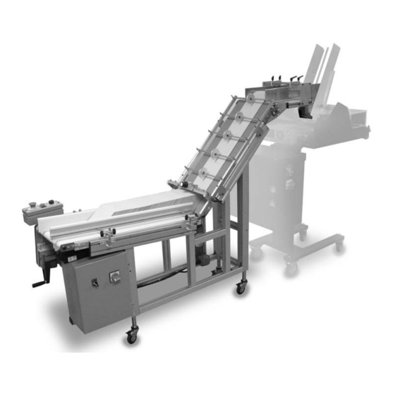
About the Machine Review the diagrams in this section to become familiar with names and locations of the parts and adjustments. This will help to prepare you for initial setup. Overview Horizontal Incline Discharge Conveyor Conveyor Area Discharge Incline Side Discharge Conveyor Guides... - Page 9 Main Assemblies Feature Descriptions Feature Description Conveyor Side Guides The conveyor side guides help direct the product in a straight line of movement on the horizontal conveyor. Discharge Belt Discharge Side Guides The discharge side guides help direct the product in a straight line of movement in the discharge area.
- Page 10 Controls Overview Speed Start/Jog Emergency Stop Operator Station On/Off Sensor Connector Main Power Control Panel HV m treAm AnuAl...
- Page 11 Controls Feature Descriptions Feature Description Speed Increases and decreases both belt speeds while maintaining the set ratio. Start/Jog Starts or jogs conveyor belts. Emergency Stop Emergency stop cuts power to unit. On/Off Main Power Sensor Connector HV m treAm AnuAl...
-
Page 12: Preparing For Operation
Preparing for Operation Overview To prepare the autoloader for operation, the follow- ing setups should be made in order: ondition of nstallment Positioning with the Feeder Warning decals must be visible to equipment operator. Discharge Side Guide Assembly and Setup Docking Conveyor Side Guide Setup DO NOT attempt to make any adjustments while the... - Page 13 Review Step 1: Positioning with the Feeder The discharge belt on the autoloader must be set slightly higher than the feeder hopper. The correct height depends on the product being fed and the clearance of the wedge being used. Objective Correctly adjust the height of the autoloader so the product being fed falls evenly and freely, without skew, into the feeder hopper.
- Page 14 Review Step 2: Discharge Side Guide The discharge side guides help direct the product in a straight line of movement along the discharge belt. Assembly and Setup Each side guide is independently adjustable, both horizontally and vertically, to accommodate different product widths.
- Page 15 Step 2: Discharge Side Guide Assembly and Setup (continued) Loosen the lock levers on each side guide. To adjust the side guides for width, indepen- dently adjust each side guide to within ap- proximately 1/8” of the product positioned as it will be received from the incline conveyor belt.
- Page 16 Review Step 3: Docking The autoloader and feeder are connected together by a docking bracket, adjustable for the distance between the feeder and the autoloader. The proper extension of the bracket will allow the proper amount of clearance for the product to fall, evenly and aligned, from the autoloader discharge belt into the hopper on the feeder.
- Page 17 Review Step 4: Conveyor Side Guide Setup The side guides help direct the product in a straight line of movement along the horizontal conveyor belt. Each side guide is independently adjustable, both horizontally and vertically, to accommodate different products. There are two locking knobs on each side guide for each adjustment.
- Page 18 Review Step 5: Separator Setup The separator shingles the product for its upward travel on the incline conveyor belt. By moving the separator up and down along the hold down frame, the height of the separator is adjusted for the height of the product as it has been loaded along the horizontal belt.
- Page 19 Review Step 6: Hold Down Rollers The hold down rollers float along the top surface of the shingled stream of product to help control it as it Setup is moved upward on the incline conveyor belt to the discharge area. The hold down rollers can be spaced as close as 3 inches along the hold down frame. The ideal set up would use the least rollers necessary to manage the product.
- Page 20 Review Step 7: Product Sensor Setup The product sensor detects when the product in the feeder hopper is low. When detected, the autoloader will advance to feed more product. Objective Properly install and adjust the autoloader product sensor. Procedure Connect the sensor to the sensor output recep- tacle on the external upper right side of the control box.
- Page 21 Review Step 8: Connect Power The autoloader must be connected to a 115VAC power source and is protected by a 15A circuit breaker. Objective Connect power and verify the circuit breaker is in the on (–) position. Procedure Open the control panel door by turning the disconnect to the off position and turning the latch/slotted screws with a screwdriver.
-
Page 22: Operation
Operation Operational Sequence Successful power-up and operation of the unit is assured if you apply each of following sets of procedures where needed: Loading product Starting/Running Product Ratio Setting Loading Product Load product uniformly between the side guides of the horizontal conveyor. Adjust side guides to allow free movement of product, about 1/8"... - Page 23 Starting/Running Product Operation (continued) Once setup is complete, turn the main power Control Panel switch to the (-) position and the On/Off switch to the ON position. On/Off Main Power On the operator station pull out the emergency Operator Station stop button.
-
Page 24: Inspection And Care
Inspection and Care Read this section to learn how to: • Visually inspect and maintain the equipment to prevent any Do not attempt to make any adjustments while operational problems or to detect part problems which may the equipment is running. Serious injury can require adjustment, replacement or cleaning. be caused by exposure to moving parts. - Page 25 Cleaning Feed Belts, Discharge Belts and O-Rings Preventive Maintenance Turn the power switch to O (off) and remove the power cord from the power source. Apply a small amount of isopropyl alcohol to a soft cloth. For belts, use moderate pressure to wipe across one belt at a Use only isopropyl alcohol (98% concentration) time while manually rotating it.
-
Page 26: Mechanical Components
Mechanical Components HV m treAm AnuAl... - Page 27 ASSEMBLIES ITEM QTY. PART NUMBER DESCRIPTION 901013 AutoloAder, llFH 311-0330 Assy, AutoloAder rAil 311-0313 Assy, sepArAtor 311-0329 Assy, Hold down wHeel 311-0324 Assy, AutoloAder product 311-0326 Assy, AutoloAder sensor 311-0387 Assy, docking Brkt HV m treAm AnuAl...
- Page 28 AUTOLOADER RAIL ASSEMBLY Assembly # : 311-0330 HV m treAm AnuAl...
- Page 29 AUTOLOADER RAIL ASSEMBLY Assembly # : 311-0330 ITEM QTY. PART NUMBER DESCRIPTION 901114 rAil, AutoloAder Hold down 901115 support, AutoloAder rAil 51277016 BAr, trAck spAcer 51277017 BAr, trAck 102688B07 sHcs #10-32 X 1 51208214 nut, t-sltdrop 1/4-20 102689B07 sHcs 1/4-20 X 1.00 102634B02 FHcs 6-32nc X 0.38 HV m...
- Page 30 SEPARATOR ASSEMBLY Assembly # : 311-0313 HV m treAm AnuAl...
- Page 31 SEPARATOR ASSEMBLY Assembly # : 311-0313 ITEM QTY. PART NUMBER DESCRIPTION 901101 plAte, sepArAtor 901104 Block, sepArAtor 901106 sHAFt, sepArAtor Ø.3125 901105 sHAFt, .375 diA X 2 901103 Block, sepArAtor Adjust 901102 Block, sepArAtor guide 901099 BlAde, AdjustABle sepArAtor 51277083 knoB 23500104 o ring, stAndArd...
- Page 32 HOLD DOWN WHEEL ASSEMBLY Assembly # : 311-0329 HV m treAm AnuAl...
- Page 33 HOLD DOWN WHEEL ASSEMBLY Assembly # : 311-0329 ITEM QTY. PART NUMBER DESCRIPTION 901168 screw, sHoulder 3/16 od X 1.00 901117 sHAFt, Hold down Ø.375 901118 roller, AutoloAder 51460090 o-ring, encoder 23500251 BeAring, oilit 3/8 X 1/2 X 3/8 104308B04 e clip 3/8 HV m treAm...
- Page 34 AUTOLOADER PRODUCT ASSEMBLY Assembly # : 311-0324 HV m treAm AnuAl...
- Page 35 AUTOLOADER PRODUCT ASSEMBLY Assembly # : 311-0324 ITEM QTY. PART NUMBER DESCRIPTION 901174 guide, MAteriAl rigHt 901173 guide, MAteriAl leFt 901177 Block, support guide 901175 Block, MAteriAl guide 43555097 HAndel 10-32 901176 sHAFt, MAteriAl guide 23500251 BeAring, oilit 3/8 X 1/2 X 3/8 51208214 nut, t-sltdrop 1/4-20 102688B04...
- Page 36 AUTOLOADER SENSOR ASSEMBLY Assembly # : 311-0326 HV m treAm AnuAl...
- Page 37 AUTOLOADER SENSOR ASSEMBLY Assembly # : 311-0326 ITEM QTY. PART NUMBER DESCRIPTION 901207 BAr, sensor Mount 435so270 knoB, 1/2 diA. #8 w/o screw 611-0108 HArness, AutoloAd 102685B03 sHcs 8-32 X .50 600624B07 MssH #2-56unc X .63 611-0109 cABle, eXtension stAck sensor HV m treAm AnuAl...
- Page 38 DOCKING BRKT ASSEMBLY Assembly # : 311-0387 HV m treAm AnuAl...
- Page 39 DOCKING BRKT ASSEMBLY Assembly # : 311-0387 ITEM QTY. PART NUMBER DESCRIPTION 901192 docking BrAcket, lip 901193 docking BrAcket, top 901317 Block, docking 901195 docking BrAcket, lAtcH 901318 Block, slide rAil 901319 Block, u-cHAnnel 901291 Block, u-cHAnnel support 901292 Block, support 51208214 nut, t-sltdrop 1/4-20 102689B07...
-
Page 40: Electrical Diagrams
Electrical Diagrams HV m treAm AnuAl... - Page 41 HV m treAm AnuAl...
- Page 42 HV m treAm AnuAl...
- Page 43 HV m treAm AnuAl...
- Page 44 HV m treAm AnuAl...
- Page 46 © 2009 Thiele Technologies, Inc. - Streamfeeder Printed in the USA.
Need help?
Do you have a question about the Thiele Streamfeeder HV and is the answer not in the manual?
Questions and answers