Table of Contents
Advertisement
Advertisement
Table of Contents

Related Manuals for Barry-Wehmiller BW Integrated Systems Streamfeeder V-1400IJ


Summary of Contents for Barry-Wehmiller BW Integrated Systems Streamfeeder V-1400IJ
- Page 1 V-1400IJ Inkjet Feeder Manual...
- Page 2 © 2018 Streamfeeder - BW Integrated Systems. All rights reserved. No part of this publication may be reproduced, photocopied, stored on a retrieval system, or transmitted without the express written consent of Thiele Technologies, Inc. - Streamfeeder. Streamfeeder - BW Integrated Systems 315 27th Avenue NE Minneapolis, MN 55418 USA (763) 502-0000...
-
Page 3: Table Of Contents
ontents Safety Information ............ii Specifications ..............iv Section 1: About the Machine ............1 Section 2: Installing the Machine ..........5 Section 3: Preparing for Operation ..........11 Section 4: How to Operate ............17 Section 5: Troubleshooting ............20 Section 6: Inspection and Care ...........22 Section 7: Mechanical Components ...........29 Section 8: Electrical Components ..........45 V-1400IJ M anual... - Page 4 efore egin Message Conventions DANGER signifies an action or specific equipment area that can result in serious injury or death if proper precautions are not taken. WARNING signifies an action or specific equipment area that can result in personal injury if proper precautions are not taken. CAUTION signifies an action or specific equipment area that can result in equipment damage if proper precautions are not taken.
- Page 5 efore egin Message Conventions Avoid injury. Do not reach around guards. Hazardous voltage. Contact will cause electric shock or burn. Turn off and lock out power before servicing. Moving parts can crush and cut. Keep guards in place. Lock out power before servicing.
-
Page 6: Specifications
peCifiCations Maximum Product Size: ...... 14 W x 18 L in (355 x 457 mm) Minimum Product Size: ...... 2 W x 3 L in (51 x 76.2 mm) Min/Max Product Thickness: ....003 -1.0 in (.07 - 25.4 mm) Belt Speed: .......... - Page 7 CertifiCation Make sure you thoroughly read this section to become familiar with all the safety issues relating to the safe operation of this product. Thiele Technologies - Streamfeeder hereby declares that this product is in conformance with the following standards: Machinery Directive 98/37/EC Low Voltage Directive IEC/EN/CSA/UL 60950 Emissions - EN55014-1...
-
Page 8: About The Machine
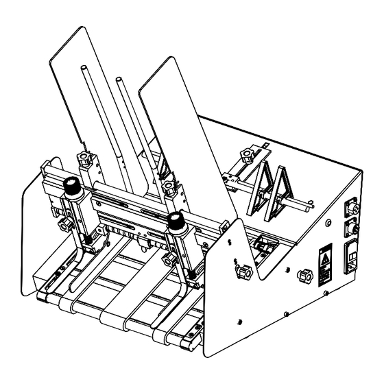
About the Machine Features The V-1400IJ is designed for reliability, flexibility, and ease of use with a variety of vacuum and non-vacuum bases. All parts required for setup, loading, feeding, and easy operator con- trol are combined into one compact unit. Review the main assemblies below to become familiar with names and locations of feeder parts and adjustments. - Page 9 Main Assemblies Feature Descriptions Feature Description Side guides Single knob adjust (one on each side) allows lateral adjustment from each side for different size product. Side guide adjustments Dual-knob design allows you to move side guides together or apart for different size product.
- Page 10 Control Features Pre-gate Bars Side Guide Side Guide Variable Lock Knob Lock Knob On Delay Speed Adjust Control Gate (inside panel Gate Adjust Knob on circuit Adjust Knob board) Gate Gate Panel Lock Knob Lock Knob Open/Close Latch Gates Run Enable Speed Switch Switch...
- Page 11 Control Features Descriptions Feature Description Variable speed control This dial switch (labeled Speed) allows the feeder speed to be synchronized with a vacuum or non-vacuum base. Turning counter- clockwise decreases speed; clockwise increases speed. Note: Feeder motor stops if turned completely counter-clockwise. Run Enable switch This slide switch allows you to use the feeder “stand- alone”...
-
Page 12: Installing The Machine
Installing the Machine This section provides information on installing the V-1400IJ onto a vacuum or non-vacuum transport base. Information for a particular application typically includes procedures for basic parts removal, feeder mounting and alignment, and cable connections for power and control interface. Information that relates to specific adjustments you must make to feeder prior to startup and operation is found in Section 3, “Preparing for Operation.”... - Page 13 STEP 1: 1. Loosen locking knobs at both side guides. Repositioning Front 2. Slide each side guide to the outermost position. Do not lock in place. Side Guides Front Side Guides Being Repositioned STEP 2: 1. Loosen each of the setscrews at the two shaft housing assem- blies A and B.
- Page 14 STEP 3: 1. Locate the gate adjustment knobs and turn completely in a clockwise direction to raise hopping rollers. Raising Hopping Rollers 2. Then, locate the vertical adjustment lever on the hopping roll- ers assembly and push down all the way. This will raise the feed rollers to highest vertical position possible, thus making for maximum clearance.
- Page 15 STEP 5: 1. Lift the feeder onto the top plate of the vacuum base and slide forward toward the vacuum base gate. Initial Positioning 2. Center the feeder between the two side guides as you posi- of Feeder tion the feeder fully forward. To verify centering, sight down the center of the feeder gate, making sure it is in-line with the vacuum base gate.
- Page 16 STEP 7: Using the run enable cables supplied for host interface applications: Connecting Dry Contact Run Enable Run Enable Input 1. Ensure power is not applied and power cord is disconnected from feeder. 2. Connect the run enable cable to the top male eight-pin thread- ed connector on the feeder.
- Page 17 STEP 8: To verify: Checking Product 1. Slide feeder back far enough to clear the vacuum base side guides. If necessary, loosen the knobs on both side guides and Discharge from Feeder pull to the outside slightly to allow movement of the feeder. 2.
-
Page 18: Preparing For Operation
Preparing for Operation Once the V-1400IJ is installed on your host system, you are then ready to prepare the machine for operation. To do so, perform the following steps: 1: Lateral feed belt adjustment 2: Gate/knockdown adjustment 3: Side guide setting 4: Back wedge adjustment 5: Verifying proper installation When performing initial feeder adjustments prior to operation, always make sure you turn Off the main power switch and... - Page 19 STEP 2: Decide whether one or two gates will be needed. This is usually based on the material size and the function of separating. They can be placed Gate/Knockdown either over the belts or over the void between belts. Adjustment 1.
- Page 20 STEP 3A: 1. Loosen each side guide lock knob. This will allow you to move each side guide individually from side to side. Side Guide Adjustment 2. Each guide is attached by a pin and slot mechanism allowing the guide to adjust vertically approximately ½ inch. To move over a feed belt, lift the side guide and move it laterally.
- Page 21 STEP 3B: (Optional) At the minimum setting (all the way toward center) the product hopper can be set to a 2" wide product. The rods are adjustable laterally to better Product Support Rod support wider products. Adjustment Loosen the shoulder bolts and move rods to desired position. Move rods laterally Loosen Loosen...
- Page 22 STEP 4: Procedure Wedge Adjustment Adjust the wedge for proper positioning following these steps: 1. Grasp a handful of product, approximately 2 to 2.5 in. (5 to 6 cm) thick, and preshingle the edges with your thumb. 2. Place the pre-shingled product in the hopper so that the edges rest against the curvature of the gate assembly.
- Page 23 STEP 5: Now that you have made all the necessary adjustments for operation, it is recommended that you verify product singulation and separation Verifying Proper at the feeder for your particular application. Before you power-up and Installation run your machine with a full hopper, manually feed several pieces of product through the gate assembly area.
-
Page 24: How To Operate
How to Operate This section provides a sequence of operation for the V-1400IJ. It also provides information for clearing a jam and for shutdown. Sequence of Successful power-up and operation is assured if you apply the follow- ing sequence of steps: Operation 1: Loading product in the hopper 2: Determining stack height... - Page 25 STEP 3: Turn the feeder power On by pushing the horizontal line (—) at the Power On/Off rocker switch. Powering On Feeder • For feeders using extenal run, feeder motor will not run until the entire base power switch is turned On (feeder On/ Off is controlled via run enable input cable).
- Page 26 Clearing a Jam If a jam occurs during operation, follow these steps: 1. Turn the feeder power Off by pushing the circle (O) at the rocker Power On/Off rocker switch. 2. Remove jammed product from feeder. While doing so, try to determine the cause of the jam (see “Troubleshooting”).
-
Page 27: Troubleshooting
Troubleshooting This table is intended to provide you with quick solutions to the more common day-to-day problems you may encounter. Problem Cause Solution No AC power to Move switch to "On" (or "—" position). 1. On/Off switch in "Off" (or "O" position). feeder Check and secure power cord at AC 2. - Page 28 Troubleshooting (continued) Problem Cause Solution Feed belts are op- Review gate assembly adjustment 5. Gate assembly may be down too tight. erating, but prod- procedure. uct not feeding 6. Too much weight in hopper. (continued) Remove product from stack. Test again. Jamming occurs A.
-
Page 29: Inspection And Care
Inspection and Care Please read this Section to learn how to: • Visually inspect your machine to detect part problems which may require adjustment or replacement. • Periodically care for your machine to prevent any opera- tional problems. When performing initial feeder adjustments prior to operation, always make sure you turn Off the main power switch and disconnect all equipment from the electrical power source. - Page 30 Visual Inspection Standard O-Ring Gate: Adjusting Worn O-Rings (continued) To adjust worn O-rings: 1. Turn Off feeder and remove power cord from outlet. 2. Remove gate(s) assembly from gate plate 3. Loosen cap screw holding o-ring spool in housing Loosen cap screw 4.
- Page 31 Preventive Care Cleaning Feed and Discharge Belts To clean feed belts: 1. Turn Off feeder and remove power cord from outlet. 2. Apply a small amount of isopropyl alcohol to a soft cloth. 3. Use your hand to move the feed belt, starting with one feed Use only isopropyl alcohol.
- Page 32 Carriage Feed Belt Removal The procedure for feed belt replacement requires the removal of Replacement the side guides, carriage saftey guard and the carriage. Side Guides: 1. Each guide is attached by a pin and slot mechanism allowing the guide to be raised vertically (see Step 3 Page 13). Lift the guide up and remove it from the pin.
- Page 33 Carriage Feed Belt Replacement Removal (continued) 4. Disengage the timing belt by slipping it over the motor pulley. Disengage timing belt. 5. Remove the carriage by pulling it out through the discharge area of the feeder. Remove carriage. Feed Belts: 6.
- Page 34 Carriage Feed Installation Belt Replacement Install new feed belts by repeating the previous steps in reverse order. (continued) Feed Belts: 1. Slip the new belts over and onto the carriage block. Position the belts equally on the carriage shafts. Install the belts. Carriage: 2.
- Page 35 V-1400IJ M anual...
-
Page 36: Mechanical Components
Mechanical Components V-1400IJ ASSEMBLIES Assembly # 311-1700 V-1400IJ M anual... - Page 37 V-1400IJ ASSEMBLIES Assembly # 311-1700 ITEM QTY. PART NUMBER DESCRIPTION 311-1720 BASE ASSEMBLY 115V 311-1704 HOPPER ASSEMBLY 311-1604 GATE ASSEMBLY 311-1721 BELT ADJUSTMENT ASSEMBLY 311-1722 CARRIAGE ASSEMBLY 311-1723 BACK PANEL ASSEMBLY 115V 311-1224 WEDGE ASSEMBLY V-1400IJ M anual...
- Page 38 BASE ASSEMBLY (115V) Assembly # 311-1720 V-1400IJ M anual...
- Page 39 BASE ASSEMBLY (115V) Assembly # 311-1720 ITEM QTY. PART NUMBER DESCRIPTION 903928 PLATE, BASE V-1400 903929 SHELL V-1400 903285 STANDOFF .26ID X .50 OD X .75LG NYLON 10501133 ASSY, MTR 90VDC V710 903930 PULLEY, TIMING 21T XL 1/2 BORE 44846058 FOOT, SUCTION CUP 51310009 LABEL, GROUND SYMBOL...
- Page 40 HOPPER ASSEMBLY Assembly # 311-1704 V-1400IJ M anual...
- Page 41 HOPPER ASSEMBLY Assembly # 311-1704 ITEM QTY. PART NUMBER DESCRIPTION 903936 BAR, TRACK V1400 311-0532 ASSY, LH SIDE GUIDE BLOCK 311-0531 ASSY, RH SIDE GUIDE BLOCK 903934 SHAFT UPPER SUPPORT 51745025 SIDE GUIDE 905367 BAR, PREGATE 51745048 SUPPORT, LH 51745056 SUPPORT, RH 51745069 BLOCK, UPPER...
- Page 42 GATE ASSEMBLY Assembly # 311-1604 V-1400IJ M anual...
- Page 43 GATE ASSEMBLY Assembly # 311-1604 ITEM QTY. PART NUMBER DESCRIPTION 23500084 GATE ADJUSTMENT 51745079 KNOB, KNURLED CONTROL 51745080 O RING 51277081 KNOB INSERT 51745073 MOUNTING FLANGE 44963102 KNOB, 5 LOBE WITH 10-32 THREADED INSERT 51745012 BLOCK, GATE SLEEVE 51745083 SPRING, GATE 334473TTI MOUNT, GATE 51805014...
- Page 44 BELT ADJUSTMENT ASSEMBLY Assembly # 311-1721 V-1400IJ M anual...
- Page 45 BELT ADJUSTMENT ASSEMBLY Assembly # 311-1721 ITEM QTY. PART NUMBER DESCRIPTION 51745030 MOUNT, SLIDE 51745038 BLOCK, STAND 903958 STANDOFF, #10 X 3/8 OD X 1.50 LG ALUM 51745041 BLOCK, END 51745040 SCREW, LH LEAD 51745078 BUSHING-USE 119679B231 51745039 SCREW, RH LEAD 51745065 BRACKET, BELT 51745064...
- Page 46 CARRIAGE ASSEMBLY Assembly # 311-1722 V-1400IJ M anual...
- Page 47 CARRIAGE ASSEMBLY Assembly # 311-1722 ITEM QTY. PART NUMBER DESCRIPTION 51745032 SHAFT, SUPPORT 900935 BLOCK, RH 900936 BLOCK, LH 903773 BELT, BLUE FEED 2” 51745035 BELT, FEED BLUE 1W 51745071 SHAFT CARRIAGE SUPPORT 435BG107 BELT, TIMING XL 55 TEETH 903931 CARRIAGE MOUNT V1400 44582021 BEARING, BALL R4 .25 BORE...
- Page 48 BACK PANEL ASSEMBLY (115V) Assembly # 311-1723 V-1400IJ M anual...
- Page 49 BACK PANEL ASSEMBLY (115V) Assembly # 311-1723 ITEM QTY. PART NUMBER DESCRIPTION 903942 PANEL, BACK V1400 903943 HINGE BACK PANEL V1400 900769 LATCH, KEYED 900770 LATCH, CAM 44675030 KNOB, SPEED POT 611-0422 ASSY, SPEED POT V1400 44642025 BOARD, SCR DRIVE 44841015 BOARD, CONTROL IJ 115V 44642026...
- Page 50 WEDGE ASSEMBLY Assembly # 311-1224 V-1400IJ M anual...
- Page 51 WEDGE ASSEMBLY Assembly # 311-1224 ITEM QTY. PART NUMBER DESCRIPTION 51745008 PLATE, WEDGE BASE 51745062 BLOCK, WEDGE 903956 WEDGE GUIDE SHAFT 903957 WEDGE SUPPORT SHAFT 43560212 WEDGE, MATERIAL SUPPORT 44963102 KNOB, 5 LOBE WITH 10-32 THREADED INSERT 44633016 ROUND T-NUT 102732B11 SSSCPPT BLACK OXIDE 10-32 X 1.00 102688B03...
-
Page 52: Electrical Components
Electrical Components 115V Assembly # 611-0418 V-1400IJ M anual... - Page 53 V-1400IJ M anual...
- Page 54 230V Assembly # 611-0419 V-1400IJ M anual...
- Page 55 V-1400IJ M anual...
- Page 57 315 27th Avenue NE · Minneapolis, MN 55418 · USA : (763) 502-0000 · F : (763) 502-0100 : service@streamfeeder.com mail : www.streamfeeder.com © 2018 Streamfeeder - BW Integrated Systems Printed in the USA.
Need help?
Do you have a question about the BW Integrated Systems Streamfeeder V-1400IJ and is the answer not in the manual?
Questions and answers