Table of Contents
Advertisement
Quick Links
Advertisement
Table of Contents

Related Manuals for Strong SRT4375


Summary of Contents for Strong SRT4375
- Page 1 Service Manual (SRT4375)
-
Page 2: Table Of Contents
Contents 1. Technical specifications 2. Block Diagram Circuit Drawing 4. List of Error codes 5 Trouble Shooting 3.1 Trouble shooting 3.2 Check point about badness STB 6. Materials list 6.1 Main PCB materials list 6.2 Front PCB materials list 7. Software download instructions(OTA and PC download) 7.1 Program Download 7.2 System Upgrade 8. -
Page 3: Technical Specifications
Technical specifications 1.1. Conditional Access Interface PCMCIA 2. Slot(type I or type II) DVB Common Interface Standard (Viaccess, Nagra Vision, Conax, Cryptoworks, Irdeto, ASTON) 1.2. Tuner & Channel <Digital Part> Input Connector F-type, IEC169-24, Female Frequency Range 950MHz to 2150MHz Input Impedance 75ohm unbalanced Signal Level... - Page 4 1.3. System & Memory Main Processor L64108(LSI-LOGIC) Flash Memort 1Mbyte Program Dram 2Mbyte EEPROM 8kbyte Channel Memory Digital Channel: 3000 (Total : 3500) Analog Channel: 500 Multi-Satellite UP to 64 Multi-Language Menu English/Spanish/French/Italian/German/Portuguese Front 7 keys, 4-digit 7–segment display Remote Controller 30-31 keys, IR Remote Control 1.4.
- Page 5 AUX Scart In/Out RGB, CVBS, L, R In CVBS, L, R Output RCA Output CVBS, L, R Output(Yellow, White, Red Hack) with Volume Control 0V/12V Output RCA Jack Output(Black Jack), Max. 150mA Data Interface RS-232, Bit Rate: 115200baud Connector: 9-pin D-sub type 1.6.
- Page 6 1.10. Environmental Condition Operating Temperature 0~40C Storage Temperature -10C~+50C Operating Humidity Range 10~85% RH, Non-condensing Storage Humidity Range 5~90% RH, Non-condensing...
-
Page 7: Block Diagram
2. Block Diagram CH_VALID, CH_CLK, CH_STRT, Block Diagram 74244 PTO[0..7] 74244 QPSK NIM Common 74244 (TBMU30311) Interface 74244 74244 8-bit BD[0..7] microcontroller Front Panel (AT89C51) TS_VALID, I2C(SDL,SCA) RS-232 TS_CLK, TS[0..7] (DS232AS) SCL, SCL,SDA RCA JACK TTXDATA, TTXREQ TXD,RXD AVD[0..7] YCRCB[0..7] CVBS EEPROM TV SCART... - Page 8 RTN3 RTN6 Q508 AUX_VOUT C520 KN3904 BLANK C521 RTN4 4.7/16 R514 RTN7 R560 VOUT R542 R541 SHIELD ILSSAN:SINGLE SCART 2203-21T AUX SCART AUX_VIN FUNC_AUX FNC_VCR UK STRONG Title SCART OUTPUT Size Document Number SRT4375 Date: Thursday, November 15, 2001 Sheet...
- Page 9 100/16 L801 L802 +5V_A S12V Q805 10uH 10uH STV12VA KTA1273 C817 C819 47/10 R853 R854 STV12XA 1.5K 4.7K C818 47/25 C820 Q806 KN3904S R855 1.5K UK STRONG Title ANALOG Size Document Number Custom SRT4375 Date: Monday, February 12, 2001 Sheet...
- Page 10 CVIN C904 C905 R901 C911 R902 KS5514B-12 4.7/16 300 MIL DIP C912 C913 R908 47/25 100K C906 0.33/50 R903 CVBS_AOSD Q900 KN3906S R904 R905 1.5K UK STRONG Title ANALOG OSD Size Document Number SRT4375 Date: Thursday, November 15, 2001 Sheet...
- Page 11 R167 3.3V R164 4.7K CON5 SENSE_CPU R165 4.7K Q157 C162 SENSE_IN C158 2.5MM PITCH KN3904S C159 C160 100/16 R152 R150 4.7K R151 Q150 KN3904S SKEW_CPU 4.7K UK STRONG Title POWER Size Document Number SRT4375 Date: Monday, February 12, 2001 Sheet...
- Page 12 BD10 D_RSTN I/O10 GPIO49 I/O09 GPIO48 AVID_SYNC I/O08 GPIO47 LOOPN I/O07 GPIO46 CASEN I/O06 GPIO45 CASEN 4.7K I/O05 GPIO44 UK STRONG I/O04 GPIO43 I/O03 GPIO42 Title CH_RST I/O02 GPIO41 L64108 I/O01 GPIO40 V_RSTN Size Document Number KM416V1204CJ-6 L64108C SRT4375 Custom...
- Page 13 XDA1 SBA1 XDA2 SBA2 XDA3 SBA3 XDA4 SBA4 XDA5 SBA5 XDA6 SBA6 XDA7 SBA7 XDA8 SBA8 TESTCLK 3.3V 4.7K RSVD RSVD RSVD UK STRONG Title L64005 Size Document Number Custom SRT4375 L64005 160p PQFP Date: Thursday, November 15, 2001 Sheet...
- Page 14 1/16 74HCT244 RESET R219 R222 R215 4.7K NC(470) PCMCIA SOCKET MODULE B R220 CA_A NC(470) Q201 KTA1273 C201 C203 1/16 UK STRONG Title R216 4.7K COMMON INTERFACE C204 C205 C206 C207 C208 C209 C210 C211 C212 C213 C214 C215 C216...
- Page 15 C316 270pF 330pF R302 100 C301 C302 15pF 15pF 22pF C318 SYSCLK 1.8uH(TDK:NL252018T-1R8J) V_RSTN BLUE L304 R310 C320 R311 C319 270pF 330pF BLANKn VSYNCn HSYNCn UK STRONG Title VIDEO ENCODER Size Document Number SRT4375 Date: Monday, February 12, 2001 Sheet...
- Page 16 10/16 DIF0 TST1 DIF1 TST2 R411 C422 R414 330P 4.3K C420 R410 U401B AK4323VF 10/16 2.7K R_AUDIO R412 KA358 R416 2.7K R415 C421 C423 47/16 UK STRONG Title AUDIO DAC Size Document Number SRT4375 Date: Thursday, November 15, 2001 Sheet...
- Page 17 C602 C601 U600 C605 C600 C604 47/16 J600 C603 BD600 FCM2012C-101 TIN1 TXD1 TIN2 RXD1 BD601 FCM2012C-101 C606 C607 DB9P-FEMALE DS232AS UK STRONG Title RS232C Size Document Number SRT4375 Date: Monday, February 12, 2001 Sheet...
- Page 18 BSTB+ RF_AUDIO AUDIOIN L172 10uH MODB+ RF_VIDEO VIDEOIN C174 SAMSUNG:TBVE18227IT R174 R175 RMUP74055VA L502 L501 10uH NC(10uH) C542 C544 C543 C545 10/50 1000/10 UK STRONG Title Tuner & Modulator Size Document Number Custom SRT4375 Date: Thursday, November 15, 2001 Sheet...
- Page 19 CH_RST DTC114 Q127 R135 PTO4 CH_ERROR DTC114 22KHz R132 PTO5 CH_STRT 2.7K/3216 PTO6 CH_VALID Q128 Q_3V PTO7 CH_CLK 22ON/OFF DTC114 Q124 LNBA_OFF DTC114 UK STRONG PTO[0..7] Title QPSK Demodulator Size Document Number Custom SRT4375 Date: Thursday, November 15, 2001 Sheet...
- Page 20 I8051BD2 RESETN P1.2 I8051BD3 P1.3 I8051BD4 PSEN P1.4 I8051BD5 ALE/P P1.5 I8051BD6 RXD2 P1.6 I8051BD7 TXD2 P1.7 GMS97C51-12MHzDIP RA701 R703 R704 4.7K 4.7K 4.7K CON14 KEY_IN UK STRONG Title MICOM Size Document Number SRT4375 Date: Thursday, November 15, 2001 Sheet...
- Page 21 1N4001 P O W E R ( S TBY) KPT1105 1N4001 UK STRONG Title F R O N T C I R C U I T Size Do c u m e n t N u m b e r...
-
Page 22: List Of Error Codes
4. List of Error codes E001: Tuner Error. E002: EEPROM Error. E003: RF Error. E004: BT864 Error. E005: L64005 Error. E006: DRAM Error. E007: STV0056 Error. E008: ATuner Error. 5. Trouble Shooting There may be various reasons for the abnormal operation of the receiver. Check the receiver according to the procedures shown below. -
Page 23: Check Point About Badness Stb
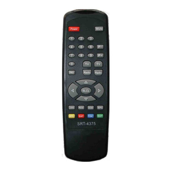
The remote controller The batteries of the Check whether the batteries Does not working. Remote controller are Are inserted correctly in your Not inserted or Remote controller. Exhausted. Check the batteries, and if Exhausted, replace the Batteries of the remote Controller. - Page 24 RESET --à Check Point : U2(12pin) CE --à Check Pint : U2(26 pin) Action) : If the flash-Rom(U2) not operation. , must be Checking chip-select pin from L64108. Replacement of part is required. Because Reset and Chip-Select signal is not Booting. Also , Checking soldering or Chip is consider flash-rom and CPU Where are replace of component Part, and Check the insertion of part...
- Page 25 if “starting boot” message is displayed, Do Download again by suitable Firmware to model. Do STB Power off/on after Download is completed. If screen is displayed, it does FACTORY RESET necessarily. 2) When Message is displayed: (Message can be different according to Firmware Version) Set ACLK <32000>...
- Page 26 When “Tuner connect Fail” Message happens If POWER supplied to Tuner is normalcy, Tuner must change. When “ FLUSH DRAM ” Message happens U50(L64005) and U51(KM416S1020) Re-soldering do, and change U50(L64005) if is happened again. Normal Message as being displayed, change MICOM if TV screen does not come 5.2.2.
- Page 27 (4) Voltage measurement supplied to TUNER 1. L100(Coil) : about 5V, L101(Coil): about 28V , U101(Regulator)-Pin 3 : about 5V U102(Regulator)-PIN 2, (C117(+)Elect Cap ) : 3.3V Action) : If voltage is normalcy TUNER change . 2. U101(Regulator)-Pin3 : 3V~ 0V Action) : If it is 100 ohm lows, doing AC POWER OFF and measure U101's(Regulator) 3Pin and resistance between GND, Tuner change...
- Page 28 Action) : Do U2(39VF800A Flash ROM) and U1(L64108 CPU) Re-solder if “Wait to Reset setting” Message comes continually when did Factory Reset. Still, change U2(39VF800A Flash ROM) if do not become. 5.2.3. POSITIONER fail (1) hen do to act AUTO LIMMIT in POSITIONER MENU SMPS side RELAY both that act confirm Action) : If RELAY in SMPS acts both, MAIN board side circuit is normalcy and most change SMPS...
- Page 29 checking, If No problem. Check the install chip-poistion and short of solder, cold solder, etc. Where are replace of component Part, Check the insertion of part CVBS --à (LOW active) RESET --à RED --à GREEN --à...
-
Page 30: Materials List
BLUE --à 6. Materials list 6.1 Main PCB materials list Item Quantity Reference Part Number VENDOR PCB main ST640V5 VER 5.0 BD150,BD151,BD152,BD153, SMB403025 TAI-Tech BD154,BD155,BD156,BD157 BD600,BD601 FCM2012C-101 TAI-Tech C1,C4,C5,C6,C7,C14,C16, CS2012Y5V104Z500NR SAMWHA C19,C20,C21,C22,C23,C25, C26,C27,C28,C51,C54,C55, C56,C57,C58,C59,C60,C61, C62,C63,C110,C112, C114,C116,C157,C158,C160, C162,C172,C174,C200,C201, C204,C205,C206,C207,C208, C209,C210,C211,C212,C213, C214,C215,C216,C300,C303, C304,C305,C321,C322,C323, C324,C401,C403,C405,C406, C416,C520,C523,C540,C542,... - Page 31 C816 C17,C826,C827,C831,C840, CS2012C0G220J500NR SAMWHA C308,C311,C315,C318 C908,C909 C18,C411,C421,C823,C825, CS2012X7R152K500NR SAMWHA C845,C849,C851,C854 CS2012C0G200J500NR SAMWHA C703,C702 CS2012C0G180J500NR SAMWHA C821,C822 CS2012COG470J500NR SAMWHA C309,C312,C316,C319 CS2012COG271J500NR SAMWHA C310,C313,C317,C320 CS2012COG331J500NR SAMWHA C422,C412 C500,C502,C504,C506, CS2012Y5V474Z160NR SAMWHA C508,C512,C513,C516,C517, C518 C501,C503,C509,C510,C514, CS2012Y5V105Z160NR SAMWHA C515,C524,C525,C900 C808,C814 CS2021X7R103K500NR SAMWHA C806,C805 CS2012C0G270J500NR SAMWHA C804,C812,C813 CS2012C0G101J500NR SAMWHA...
- Page 32 RA50,RA51,RA52,RA100,RA101 CN 164 101 JT HAN RYUK RA102,RA204,RA205 R2,R13,R26,R36,R37, CR 1/10 102 JT HAN RYUK R153,R156,R166,R170, R200,R207,R208,R406,R416, R517,R519,R521,R525,R537, R541,R544,R546,R550,R580, R581,R582,R802,R813,R815, R819,R901,R902,R903,R905 R10,R14,R16,R17,R50, CR 1/10 472 JT HAN RYUK R55,R106,R109,R136 R150,R151,R155,R159, R164,R165,R201,R202,R554 R203,R204,R205,R206,R209, R210,R211,R212,R215,R216, R704,R707,R812,R814,R825, R828,R854,R703,R708 R710,R711,R712,R38 R3,R4,R5,R6,R107, CR 1/10 103 JT HAN RYUK R108,R173,R502,R503,R543, R548,R551,R556,R557,R558,...
- Page 33 R404,R414,R523,R524,R527, CR 1/10 473 JT HAN RYUK R528 R405,R415,R842,R851 CR 1/10 243 JT HAN RYUK R500,R501,R506,R508,R510, CR 1/10 622 JT HAN RYUK R511,R515,R516 R507,R509,R512,R513,R514, CR 1/10 750 JT HAN RYUK R518,R520,R522,R526,R534, R538,R542,R545 R530,R531,R532,R533,R535, CR 1/10 621 JT HAN RYUK R536,R539,R540 R547 CR 1/10 510 JT HAN RYUK...
- Page 34 U401 KA358D Fairchild U500 CXA2078Q Sony U600 DS232AR SOIC-16 V D1,VD2 1SV215 Toshiba Item Quantity Reference Part Number VENDOR C906 RSS/TA-0.33/50-5*11*5 DAEWOO C111,C115,C117 RSS/TA-47/25-5*11*5 DAEWOO C413,C423,C505,C604 C415,C818,C913 C173,C325,C817 C154,C155,C156 RSS/TA-47/50-6.3*11*5 DAEWOO C521,C522,C903,C911 RSS/TA-4.7/50-5*11*5 DAEWOO C13,C24,C64,C700,C705 RSM/TA-10/25-5*7*5 DAEWOO C171,C400,C402,C404,C410, C420,C526,C527,C528,C529, C530,C531,C532,C533,C541, C580,C581,C809,C810,C811, C830,C842 C113,C544...
-
Page 35: Front Pcb Materials List
U204,U203 PALCE22V10H-25PC/4 U204,U203 socket 4000-24SD-3 ILSSAN U700 AT89C51-16PI ATMEL U700 socket 4000-40SD6-1 ILSSAN U801 STV0056A U900 KS5514B-12 SAMSUNG X1(27MHz X -tal) HC-49/U Kony X700(11.0592MHz X-tal) 11.0592MHz(crytal) SHINYOUNG X801(4MHz X-tal) 4MHz SHINYOUNG X900(17.734475MHz X-tal) 17.734475MHz SHINYOUNG TT2, BIN(+)*WTH 3*6 (BLACK) T SMPS-P-108P0 SMPS ;... -
Page 36: System Upgrade
Firmware download You can download firmware to receiver Press “BROWE” button to select firmware (ELF) to downloading. After selecting firmware, you can start downloading by pressing “START” button. You can see progressing bar while downloading The receiver will automatically restart when downloading is finished. Channel Information upload You can save channel information of receiver to PC file by using this function You have to select a file to save in PC by pressing “BROWSE”... -
Page 37: Specification Of Required Cables For Software Download
1. Please wait while your receiver is checking if your software version is the newest one available. 2. If you already have the newest version noting will happen, and you can leave the menu. When you need the newest version software, the receiver will automatically download that version from the satellite signal.
Need help?
Do you have a question about the SRT4375 and is the answer not in the manual?
Questions and answers