Table of Contents
Advertisement
Advertisement
Table of Contents

Related Manuals for GT POWER GT2500i


Summary of Contents for GT POWER GT2500i
- Page 1 GT2500i 2400W...
- Page 2 Congratulations on your new GT Power product! The GT Power range from Euroquip uses latest technology design and engineering to produce generator products that combine market leading value and features with durability. Designed for discerning operators who seek professional results and product quality. Design emphasis is placed on simple, functional design and operation.
-
Page 3: Table Of Contents
Table Of Contents Safety Definitions ..............4 General Safety Precautions .............4 Safety Labels................6 Unpacking the Generator............7 Accessories................7 Generator Controls & Features ..........8 Before Starting the Generator..........10 Checking and Adding Engine Oil and Fuel......11 Starting the Generator............12 Stopping the Generator............14 Application and Duty Cycle............15 Ambient Conditions..............15 Connecting Electrical Loads..........15 240V AC Extension Cords............17... -
Page 4: Safety Definitions
Safety Definitions General Safety Precautions The words DANGER, WARNING, CAUTION and NOTICE are used throughout this manual DANGER! to highlight important information. Be certain Never use the generator in a location that the meanings of these alerts are known that is wet or damp. Never expose the to all who work on or near the equipment. - Page 5 • Never operate the engine if a fuel leak is • Never touch live terminals or bare wires discovered. while the generator is operating. • Equip the operating area with a Class ABE • Keep animals and children away from the or BE portable fire extinguisher.
-
Page 6: Safety Labels
This generator pr o duces ext reme heat. The muffler and surr ounding ar eas get very hot and sever e burning will occur if in contact with skin. Power Factor: 1.0 Model Number: GT2500i AC Outlet: Rated Power: 2100W IP Rating: Starting Power:... -
Page 7: Unpacking The Generator
Accessories the Generator Check the accessories against those listed below. If any parts are missing, please con- tact your local GT Power dealer. WARNING! Always have assistance when lifting • 400 ml Bottle of SAE 15W-40 Engine Oil the generator. The generator is heavy;... -
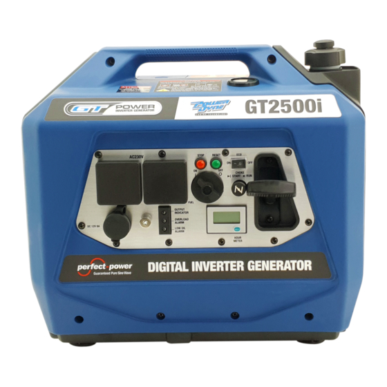
Page 8: Generator Controls & Features
Generator Controls and Features 1 - Carry Handle 2 - Fuel Gauge 3 - Fuel Cap and Vent 4 - Air Filter Access Cover 5 - Recoil Starter Handle 6 - Control Panel (Fig. 2) Generator Controls and Features 1 - Spark Plug Access Cover 2 - Muffler Access Cover 3 - Spark Arrester 4 - Oil Access Cover... - Page 9 (Fig. 3) Front Panel Controls & Features 1. 230-Volt AC, 15-Amp Outlets voltage when generator is running. Press the Each outlet is capable of delivering generator switch on its fascia to illuminate the meter and then cycle through the engine speed and cu- peak output of 2400W (i.e.
-
Page 10: Before Starting The Generator
NOTICE: Only operate the generator on a the engine is running and there’s AC output available from the generator. solid, level surface. 11. Frame Terminal Operating the generator on a surface with The frame terminal can be used by a licensed loose material such as sand or grass clip- electrician to earth the generator if necessary. -
Page 11: Checking And Adding Engine Oil And Fuel
See Engine Oil Maintenance on pages 22 - WARNING! 24 for more information Be sure the generator is properly in- stalled to reduce the possibility of elec- NOTICE: The generator does not contain tric shock. Any connection to an elec- engine oil as shipped. -
Page 12: Starting The Generator
Starting the 6. Remove the fuel cap by unscrewing it anticlockwise. Generator 7. Slowly add fuel into the fuel tank. Be careful not to overfill the tank. The fuel Before attempting to start the generator, ver- level should NOT be higher than the red ify the following: ring inside the fuel strainer (see Figure 6). - Page 13 (Fig. 7) Choke Knob in START Position (Fig. 5) Fuel Cap Vent in ON Position (Fig. 6) Fuel Control Switch in ON Position (Fig. 8) Recoil Starter Handle Operation 1. Turn the fuel cap vent clockwise to the Do not allow the starter handle to snap ON position.
-
Page 14: Stopping The Generator
1. Turn off and unplug any electrical devices or cords from the 230V AC and 12V DC receptacles on the control panel. 2. Press the generator reset button on the control panel until the overload alarm light goes off and the output indicator light is illuminated green. -
Page 15: Application And Duty Cycle
Application & Duty Cycle All models within this range of GT Power gen- erators are portable, air-cooled, petrolengine driven, self-contained units designed for in- dependent supply of electrical power. They... - Page 16 NOTICE: DO NOT connect any 230V AC de- The generator’s total power output measured in Watts is listed in the Specifications (see vice that is fitted with a three-pin 20A plug. This can overload the generator. page 37). See 230V AC Extension Cords on page 17 Two 230V AC power outputs are specified for for detailed instructions concerning their se- the generator, namely the running power and...
-
Page 17: 240V Ac Extension Cords
1. Use only the shortest possible extension ceed 2100W for the GT2500i. cord for the task. Voltage drop increases proportionately with the length of an ex-... -
Page 18: Battery Charging
A. By direct connection to the generator’s tension cord and may result in damage to 12V DC electrical outlet; or the powered device. B. By using a mains-powered 12 Volt battery 2. Use only a single extension cord and not charger connected to one of the genera- multiple cords joined together. - Page 19 just above the internal battery plates. This 10. Disconnect the negative (-) alligator clip may not be possible with a maintenance- (black) from the negative (-) terminal on free battery. the battery. 11. Disconnect the positive (+) alligator clip 2. Connect the positive (+) alligator clip (red) to the positive (+) terminal on the battery.
-
Page 20: Transporting The Generator
Transporting the in accordance with its operating instruc- tions. Generator 6. Insert the battery charger’s power supply The generator should be stopped and both plug into one of the generator’s 240-Volt the fuel control switch and fuel cap vent AC outlet sockets and then switch the should be turned to the OFF position before battery charger ON. - Page 21 Prolonged skin contact with en- only as a general minimum guideline. Use gine oil or fuel can be harmful. Fre- only genuine GT Power spare parts or others quent and prolonged contact with en- as specified herein. Non-genuine spare parts gine oil may cause skin cancer.
-
Page 22: Engine Oil Maintenance
It is recommended to engage an au- engine. thorised GT Power service dealer to carry out this work. Engine oil level should be checked before every use. - Page 23 6. Remove oil fill plug. 7. Select the proper engine oil as explained in Engine Oil Specification on page 22. 8. Using the supplied oil fill bottle, slowly add engine oil to the engine (see Fig. 13). Check the oil level periodically to avoid overfilling.
-
Page 24: Air Filter Maintenance
3. Remove the oil access cover on the rear proper disposal of hazardous materials. Con- of the generator (see Fig. 10). sult local authorities or reclamation facility. 4. Place oil pan or other suitable container under the oil fill plug. Air Filter 5. - Page 25 7. Rinse air filter element by immersing it in fresh water and applying a slow squee zing action. NOTICE: Never dispose of the used clean- ing solution or solvent by dumping it into a sewer, on the ground, into groundwater or into a waterway.
-
Page 26: Fuel Strainer Maintenance
Fuel Strainer Keep the fuel strainer vertical so that any trapped liquid or solids do not spill onto Maintenance the generator. Check and clean the fuel strainer after every 8. Pour the contents of the fuel strainer into 100 hours of use or 6 months. It is recom- a suitable waste receptacle. -
Page 27: Spark Plug Maintenance
Spark Plug Maintenance Tools required - Spark plug socket wrench (included), spark plug gap tool or feeler gauge (not included) and wire brush (not included). The spark plug should be checked and cleaned after every 100 hours of use or 6 Figure 21 –... -
Page 28: Spark Arrester Maintenance
Spark plug gap within the acceptable b - Use a spark plug socket wrench to finish tightening the spark plug. If re- limits of 0.6 - 0.7mm or 0.024 - 0.028 inch (see Fig. 23). installing a used spark plug, tighten 1/8 to 1/4 of a turn after the spark plug - After cleaning with a wire brush, check seats. -
Page 29: Cleaning The Generator
Cleaning the Generator The generator should be kept clean and dry at all times to ensure its reliable and safe op- eration.This must be checked each time be- fore using the generator. Use a damp cloth which has been soaked in a mixture of household detergent and warm Figure 25 - Removing the Spark Arrester water and then wrung out to remove excess... -
Page 30: Draining The Fuel
5. Turn the fuel control switch clockwise to the ON position (see Figure 6). 6. Using a flat blade screwdriver, remove the fuel drain access cover (see Fig 33) 7. Position a fuel storage container to collect fuel discharged from the drain hose (see Fig. -
Page 31: Long Term Storage
13. Re-install the fuel cap. 1. Clean generator as outlined on page 29. 14. Turn the fuel cap vent anti-clockwise to 2. Add GT Power Fuel Set or another fuel the OFF position. stabiliser to the fuel tank and then add fresh fuel up to the tank’s maximum ca-... -
Page 32: Dismantling And Disposal
pacity (see checking and Adding Fuel on pull the recoil starter handle to rotate the page 11). engine several times. This will distribute the oil and protect the cylinder wall from 3. Start generator and run it for 10 minutes corrosion during storage. -
Page 33: Troubleshooting
Dispose of these hazardous items only ised GT Power service dealer. at an authorised waste collection / recycling facility. Before dismantling: Do not pollute the environment by improper 1. - Page 34 12. Spark arrestor is dirty or 12. Check spark arrestor - clean if necessary. blocked. 13. If above possible causes 13. Take generator to an authorised GT Power are checked and eliminated, service dealer. generator may be faulty. 1. Check connected electrical cord(s) or 1.
- Page 35 Damage caused to generator by excessive or faulty 12V DC loads is not covered by warranty. 4. If above possible causes 4. Take generator to an authorised GT Power are checked and eliminated, service dealer. generator may be faulty.
-
Page 36: Calculating Your Power Needs
230V AC load. If only single load, check running and starting power demands versus generator’s rating. 8. If above possible causes 8. Take generator to an authorised GT Power are checked and eliminated, service dealer. generator may be faulty. -
Page 37: Wattage Reference Guide
Wattage Reference Guide Appliances Approx Approx Appliances Approx Approx Run (W) Start (W) Run (W) Start (W) Microwave 750W 1200 Central Air Conditioner: Coffee Maker 1750 1750 10,000 BTU 1500 2200 Electric Clothes Drier 5750 5750 24,000 BTU 3800 5000 Washing Machine 1150 2300... -
Page 38: Specifications
Specifications ENGINE: Type 1-Cylinder, 4-Stroke, Overhead Valve, Air Cooled Displacement (cm3) Speed (rpm) 3200 ~ 5000 Rated Power (kW / hp) 2.6 / 3.5 Oil Capacity (mL) Low Oil Shutdown Spark Plug Torch A5RTC Fuel NGK CR5HSA Fuel Tank Capacity (L) Fuel Gauge Starting Method Recoil... -
Page 39: Wiring Diagram
Wiring Diagram www.gtpower.co.nz... -
Page 40: Warranty
Registered warranty period for the GT2500i product. Commercial Use: 24 Months Should any issue be found to be a combination of... - Page 41 Serial Number: ___________________________ Model:__________________________________ Date Purchased:__________________________ Retailer Purchased From:___________________ Scan here to register your product www.gtpower.co.nz Please attach your proof of purchase here. www.gtpower.co.nz...
- Page 42 Notes www.gtpower.co.nz...
- Page 43 www.gtpower.co.nz...
- Page 44 Congratulations on your new GT POWER product. We are proud to have you as our customer and will strive to provide you with the best service and reliability in the industry. This product is backed by our extensive warranty and service network.
Need help?
Do you have a question about the GT2500i and is the answer not in the manual?
Questions and answers