Table of Contents
Advertisement
Advertisement
Table of Contents

Related Manuals for GT POWER GT4000ESi


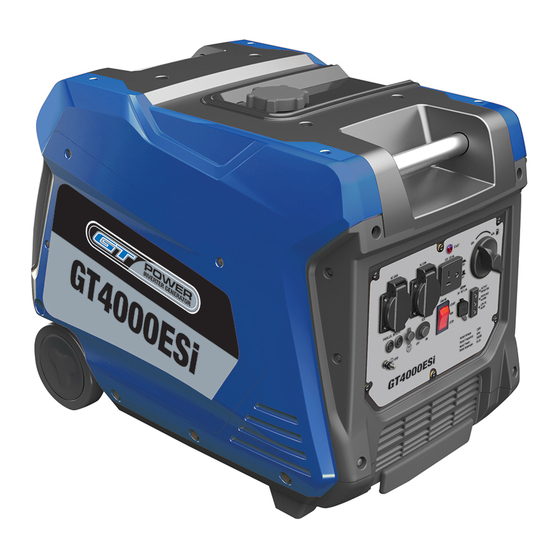
Summary of Contents for GT POWER GT4000ESi
-
Page 2: Table Of Contents
Contents Introduction..................3 Environmental protection..............3 Scope of product................3 Description of symbols..............3 Specifications...................3 Safety instructions.................4 Know your product................8 Unpacking..................8 Control panel...................9 Approximate wattage requirements..........10 Connecting the battery..............11 Powercords..................11 Before starting................12 Preparation..................13 Adding engine oil................14 Adding fuel..................14 Starting the generator..............15 Stopping the generator..............17 Maintenance...................18 Cleaning the generator ..............23 Battery replacement...............24... -
Page 3: Introduction
Description Of Introduction Symbols Your new GT POWER Generator will more than satisfy your expectations. It has been manufactured under The rating plate on your tool may show symbols. stringent quality standards to meet superior These represent important information about the performance criteria. -
Page 4: Safety Instructions
Safety Instructions 7. Dress correctly. Do not wear loose clothing or jewellery. They can be caught in moving parts. Rubber gloves and non-slip footwear are To use this tool properly, you must observe the safety recommended when working outdoors. If you have regulations, the assembly instructions and the long hair, wear a protective hair covering. - Page 5 www.gtpower.co.nz...
- Page 6 www.gtpower.co.nz...
- Page 7 1. Do not operate in a hazardous location. Such also ignite with the hot engine. Never refuel whilst the engine running. areas include where there is a risk of explosion of petrol fumes, leaking gas or explosive dust. 7. Be careful where you store the generator. Store 2.
-
Page 8: Know Your Product
1 x Quick Start Guide Due to modern mass production techniques, it is WARNING! unlikely that your GT POWER Generator is faulty or You MUST unplug any load from the generator that a part is missing. If you find anything wrong, do... -
Page 9: Control Panel
10.Parallel Outlets: Optional Cables connect 2 x GT POWER machines to increase power output. OUTPUT DO NOT attempt to parallel the GT POWER generator INDICATOR with any other manufacturers’ generators. OVERLOAD See pg 12 for more information. -
Page 10: Approximate Wattage Requirements
Approximate Wattage Requirements IMPORTANT: Always check that the combined load of your appliances does not exceed the rated output of your generator. Always select a generator that has more capacity than your load requirements. The small amount extra you may invest to do this will be quickly recovered with the fuel saving and longer service life gained by not having to constantly run your generator at full... -
Page 11: Connecting The Battery
Powercords Using Extension Cords GT POWER assumes no responsibility for the content within this table (on the following page). The use of this table is the responsibility of the user only. This table is intended for reference only. -
Page 12: Before Starting
Before Starting The parallel connection is a feature that allows two Before starting the inverter, review the safety section GT4000ESi machines to be connected together in this manual. almost doubling the output of one unit. Check your wattage reference guide and be sure the device you connecting is less than the rated use of this generator in parallel use (see specifications). -
Page 13: Preparation
DANGER! WARNING! Using a generator indoors can kill you in minutes. Be sure the generator is properly connected to Generator exhaust contains carbon monoxide. earth ground before operating. This is a poison you cannot see or smell. High Altitude Operation - Engine power is reduced the higher you operate above sea level. -
Page 14: Adding Engine Oil
3. Using the supplied funnel and oil, pour the entire WARNING! bottle of oil into the engine. See correct oil level in Do not operate a device while it is plugged into Figure 4 below. the 12V DC outlet. Prolonged exposure to engine exhaust can cause serious injury or death. -
Page 15: Starting The Generator
Only use gasoline that meets the following require- Before attempting to start the generator, verify the following: ments: • Unleaded gasoline only • The engine is filled with engine oil (see Figure 4: • Gasoline with maximum 10% ethanol added Engine Oil Correct Level on page 14). - Page 16 6. Turn battery switch ON. 7. Push and hold the engine start push button for 1 second and release (see Figure 7). The engine will automatically set the choke and begin the start sequence. Figure 8: Pull the Recoil Handle out from generator Figure 7: Electric Start Button - PUSH Wireless Remote Start 8.
-
Page 17: Stopping The Generator
Stopping the 2. If no load is present, the generator RPM will drop down to an idle speed. Generator 3. As a load is applied, the generator will sense the Normal Operation load and engine RPM will increase according to the load applied. -
Page 18: Maintenance
Maintenance CAUTION! Avoid skin contact with engine oil or gasoline. Note: Before performing maintenance on the Prolonged skin contact with engine oil or generator, review the safety section in this manual as gasoline can be harmful. Frequent and well as the following safety messages. prolonged contact with engine oil may cause skin cancer. - Page 19 Engine Oil Maintenance 7. Check oil level: When checking the engine oil, remove the oil fill/ drain plug. NOTE: Always maintain proper engine oil level. • The oil level is acceptable if oil is visible at the Failure to maintain proper engine oil level could result bottom of the threads of the oil fill plug.
- Page 20 Cleaning the Air Filter CAUTION! Never use gasoline or other flammable solvents to clean the air filter. Use only household deter- gent soap to clean the air filter. Figure 13: Squeezing air filter under water The air filter must be cleaned after every 50 hours of 4.
- Page 21 Draining the Float Bowl NOTE: Never dispose of fuel by dumping fuel into a sewer, on the ground, or into groundwater or water- ways. Always be environmentally responsible. Follow 1. Remove the Engine Service Panel to access the the guidelines of the EPA or other governmental carburetor (see Figure 11).
- Page 22 5. Clean area around the spark plug. c. Replace the spark plug boot, making sure the boot fully engages the spark plug’s tip. 6. Using the spark plug socket wrench provided, remove the spark plug from the cylinder head (see d.
-
Page 23: Cleaning The Generator
7. Using a wire brush, remove any dirt and debris that 3. Rotate the engine to top dead center (TDC) of the may have collected on the spark arrestor screen. compression stroke. Looking through the spark plug hole, the piston should be at the top. 8. -
Page 24: Battery Replacement
Battery Storage Replacement WARNING! 1. Remove the spark plug wire from spark plug. Never store machine with fuel in the tank or in a poorly ventilated area where the fumes can 2. Loosen the rubber strap holding the battery in come in contact with an ignition source such place. -
Page 25: Troubleshooting
Troubleshooting PROBLEM POTENTIAL CAUSE SOLUTION 1. Reset breaker is tripped. 1. Reset the reset breaker. 2. The power cord’s plug connector is not fully engaged in the generator’s outlet. in the generator’s outlet. Engine is running, but no 3. Faulty or defective power cord 3. -
Page 26: Parts Diagram
Parts Diagram www.gtpower.co.nz... -
Page 27: Parts List
Parts List Part. Description 100561 Enclosure Top 100578 Damper 100560 Side Panel 100562 Enclosure Side 100566 Access Cover 100567 Lift Bar 150527 Vent Hose 150526 Fuel Tank 150529 Strainer 120538 Inverter Module 150534 Fuel Filter 100569 Intake Grate 150536 Hose Clamp 150535 Fuel Valve 170514... -
Page 28: Engine Parts Diagram
Engine Parts Diagram www.gtpower.co.nz... -
Page 29: Engine Parts List
Engine Parts List Part. Description 180581 Dip Stick 180582 Low Oil Switch 170516 Starter 180580 Spark Plug 170512 Recoil and Housing 160504 Air Box 100548 M6 Nut 140517 Gasket 140532 Carburetor Assembly 140531 Stepper Motor Bracket 140533 M4X25 140529 Stepper Motor 140530 Stepper Motor 140534... -
Page 30: Wiring Diagram
Wiring Diagram www.gtpower.co.nz... -
Page 31: Warranty
Registered warranty period for: customers’ full responsibility. GT4000ESi Commercial Use: 12 Months as a warranty claim is made at the sole jurisdiction Domestic Use: 12 Months of Euroquip. - Page 32 Congratulations on your new GT POWER product. We are proud to have you as our customer and will strive to provide you with the best service and reliability in the industry. This product is backed by our extensive warranty and world-wide service network. Please contact your local agent or submit...
Need help?
Do you have a question about the GT4000ESi and is the answer not in the manual?
Questions and answers