Advertisement
Quick Links
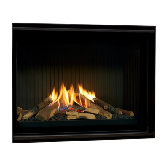
VECKTOR CAMPFIRE FLAME
EFFECT SPACE HEATER XLC
FLUE CONFIGURATIONS
POLYPROPYLENE FLUE INSTALLATION
SUPPLEMENT INSTRUCTION MANUAL
The Vektor
space heater is suitable to be installed into a frame out
installation. Designed to operate on Natural gas.
Approval no. GMK 10622
VERSION 2
Advertisement

Related Manuals for RealFlame Vektor 1100


Summary of Contents for RealFlame Vektor 1100
- Page 1 VECKTOR CAMPFIRE FLAME EFFECT SPACE HEATER XLC FLUE CONFIGURATIONS POLYPROPYLENE FLUE INSTALLATION SUPPLEMENT INSTRUCTION MANUAL The Vektor space heater is suitable to be installed into a frame out installation. Designed to operate on Natural gas. Approval no. GMK 10622 VERSION 2...
- Page 2 You must register to receive the benefit of this warranty by completing the warranty registration on our website (www.realflame.com.au) or completing and mailing the attached registration card within 30 days of purchase of your Gas Burner (or, if the Gas Burner is fitted to a new home, within 30 days of the date of settlement of purchase of such new home).
- Page 3 INSTALLATION NOTICE The installation of this appliance is only to be carried out by an authorized person in accordance with the Manufacturer’s Instructions, local gas fitting regulations, AS/NZS5601.1-2013 installation code for gas burning appliances and any other relevant statutory regulations. In all cases the installation of this appliance shall meet the requirements as set out in AS/NZS5601.1-2013.
- Page 4 CONTENTS Contents ........................4 Installation instructions ................... 5 Poly Pro General Installation Requirements ............5 Vektor Standard 5 -13.5m - Wall Mounted Fan ............ 10 Setup with External Wall Mounted Fan Terminal............. 21 Glen Dimplex contact information ................. 37...
- Page 5 INSTALLATION INSTRUCTIONS THIS INSTRUCTION MANUAL MUST BE READ IN CONJUNCTION WITH THE VEKTOR XL INSTALLATION AND OPERATING INSTRUCTION MANUAL INSTALLATION CODES Note appliance gas type – Natural gas. Should the appliance be the incorrect gas type, please contact the supplier. Installers –...
- Page 6 INSTALLATION INSTRUCTIONS (continued) FLUE TERMINATION LOCATION This section is used to determine where your flue termination will be located. • Flue terminations shall not be recessed in walls or sidings. • EXTREMELY IMPORTANT: In heavy snow areas take extra care to prevent blocking flue termination with snow removal equipment.
- Page 7 POLY PRO GENERAL INSTALLATION REQUIREMENTS (continued) Joint Connections Verify the gasket is seated evenly inside the groove in the female end. For PP/Metal pipe with a locking tab, slide locking band on male pipe section. Insert locking tab into locking band recess, rotate button away from locking band clasp, insert pipe sections, push lock band clamp downward into socket, disengage socket/tab 1/4˝...
- Page 8 POLY PRO GENERAL INSTALLATION REQUIREMENTS (continued) The venting system shall be securely supported using suitable hangers. Duravent hardware is recommended; field supplied support hardware suitable to the AHJ is acceptable, hardware must not deform on damage the vent. Make sure the load on the vent system is not supported by the appliance.
- Page 9 SETUP WITH EXTERNAL WALL MOUNTED FAN TERMINAL Maximum 13.5m flue length Instructions are in 3 sections 3. Intake pipe connection 4. Flue exhaust connections 5. Wall mount controller setup...
- Page 10 SETUP WITH EXTERNAL WALL MOUNTED FAN TERMINAL Wall mounted fan terminal IMPORTANT INSTALLATION NOTES · Flexi flue must be fully extended to length. 5m for exhaust flue and 2 x 7m for inlet. · 5m of flexi flue on the exhaust side MUST be fully extended and used before prior to converting to polypropylene.
- Page 11 INSTALLATION INSTRUCTIONS Intake pipe connection to appliance Flexi flue is provided for air intake. A maximum of 2 x 7m lengths can be used. Cut tube to length where required. Ensure ends are burr free and round, test fit flue will slide over connection.
- Page 12 INSTALLATION INSTRUCTIONS (continued) Slide flue onto connection spigot fully. Tighten clamp fully. Wipe excess silicon, visually check connection to ensure connection is fully sealed. Intake pipe joiner connection Ensure ends are burr free and round, test fit flue will slide over connection joiner. Apply an 8mm thick silicon bead fully around both ends of connector approx.
- Page 13 INSTALLATION INSTRUCTIONS (continued) Intake pipe joiner connection (continued) Apply an 8mm silicon bead fully around the inside of the flue ends. Fit flue clamp over flue ends (loosely). Slide each flue halfway onto connection joiner. Tighten clamp fully. Wipe excess silicon, visually check connection to ensure connection is fully sealed.
- Page 14 INSTALLATION INSTRUCTIONS (continued) Remove main assembly from the rear wall mounting plate assembly. Remove the 5 screws as shown. (Do not remove fan plate screws) Lift off main fan terminal assembly. Remove wall mount plate from flue connection plate. Cut air intake flue to length (Approximately 70mm through wall exit).
- Page 15 INSTALLATION INSTRUCTIONS (continued) Push connection plate into approximate position. Push flue through intake socket and fit flue holding screw. Locate wall mounting bracket into position Locate wall mounting bracket into position and affix to wall.
- Page 16 INSTALLATION INSTRUCTIONS (continued) Assemble spigot connection plate assembly to wall mounting bracket. (4 screws) Flue exhaust connections - Inlet connection to appliance Note: The full 5m of flexi flue must be used. Fully extend the 5m aluminium flexi flue. NOTE FULL LENGTH MUST BE USED.
- Page 17 INSTALLATION INSTRUCTIONS (continued) Apply an 8mm silicon bead fully around the inside of the flue ends. Fit flue clamp over flue ends (loosely). Slide flue onto connection spigot fully. Tighten clamp fully. Wipe excess silicon, visually check connection to ensure connection is fully sealed. Aluminium to Poly Pro flue connection Note: A total of 5m of aluminium flexi flue must be used prior to the joiner.
- Page 18 INSTALLATION INSTRUCTIONS (continued) Fit flue clamp over flue (loosely). Slide flue onto connection spigot fully. Tighten clamp fully. Wipe excess silicon, visually check connection to ensure connection is fully sealed. Apply a light soapy water film to the gasket and the tube end.
- Page 19 INSTALLATION INSTRUCTIONS (continued) Poly Pro to wall mounted fan module connection Ensure mounting plate is affixed to wall bracket. Verify gasket is sitting correctly in condensate drain connection. Apply a light soapy water film to the gasket and the tube end. Insert pipe fully into end fitting, Pipe will push in smoothly and evenly, should this not occur remove pipe and reseat gasket.
- Page 20 INSTALLATION INSTRUCTIONS (continued) Connect power cable connector. Fit cable clamp to cable. Fit front cover.
- Page 21 INSTALLATION INSTRUCTIONS (continued) SETUP WITH APPLIANCE MOUNTED FAN OR INLINE MOUNTED FAN AND WALL TERMINAL Maximum 13.5m flue length Instructions are in 3 sections - Intake pipe connection - Flue exhaust connections - Wall terminal setup NOTE – A MINIMUM OF 3 DEG. DRAINAGE FALL MUST BE INSTALLED IN THE POLY PRO FLUE.
- Page 22 INSTALLATION INSTRUCTIONS (continued) IMPORTANT INSTALLATION NOTES · Flexi flue must be fully extended to length. 5m for exhaust flue and 2 x 7m for inlet. · 5m of flexi flue on the exhaust side MUST be used before prior to converting to polypropylene.
- Page 23 INSTALLATION INSTRUCTIONS (continued) Air intake pipe - Intake pipe connection to appliance (continued) Flexi flue is in 7m lengths. A maximum of 2 lengths can be used. Apply an 8mm silicon bead fully around the inside of the flue end (heater connection end) Fit flue clamp over flue (loosely).
- Page 24 INSTALLATION INSTRUCTIONS (continued) Air intake pipe - Intake pipe joiner connection (continued) Apply an 8mm thick silicon bead fully around both ends of connector approx. 10mm from the ends. Apply an 8mm silicon bead fully around the inside of the flue ends. Fit flue clamp over flue ends (loosely).
- Page 25 INSTALLATION INSTRUCTIONS (continued) Air intake pipe - Intake connection to wall mounted fan terminal Locate terminal on wall and predrill mounting holes where required. Cut flue inlet tube to length (Flue must extend a minimum of 50mm past the exit face of wall.) It is recommended that the tubes are cut slightly longer and pushed back into wall upon fixing of wall terminal.
- Page 26 INSTALLATION INSTRUCTIONS (continued) Flue Exhaust Connections - Connection to fan module at appliance (continued) Note: 5m of flexi flue on the exhaust side MUST be used before prior to converting to polypropylene. Failure to do this will result in appliance shutdown. Apply an 8mm silicon bead fully around the inside of the flue end, both ends.
- Page 27 INSTALLATION INSTRUCTIONS (continued) Flue Exhaust Connections - Connection to fan module at appliance (continued) Locate 2nd clamp onto lower connection and tighten clamp fully. Wipe excess silicon, visually check connection to ensure connection is fully sealed. Where fan sits higher, ensure fan assembly is supported on a frame. Where timber framing is used clearances to flue and fan box must be maintained.
- Page 28 INSTALLATION INSTRUCTIONS (continued) Flue Exhaust Connections - Fit hot exhaust flue pipe from outlet termination to fan outlet connection (continued) Slide flue onto connection spigot fully. Tighten clamp fully. Wipe excess silicon, visually check connection to ensure connection is fully sealed. Connect power cable to fan module Flue Exhaust Connections - Aluminium to Poly Pro flue connection Ensure ends are burr free and round, test fit flue will...
- Page 29 INSTALLATION INSTRUCTIONS (continued) Flue Exhaust Connections - Aluminium to Poly Pro flue connection (continued) Fit flue clamp over flue (loosely). Slide flue onto connection spigot fully. Tighten clamp fully. Wipe excess silicon, visually check connection to ensure connection is fully sealed. Apply soapy water to oring in Poly Pro flue and dampen surface of connector.
- Page 30 INSTALLATION INSTRUCTIONS (continued) WALL TERMINAL WITH CONDENSATE MOUNTING Locate terminal on wall and predrill mounting holes where required. Markout the required penetration area. Cutout the area in wall for the flue pipes and condensate drain. (NOTE - Access to rear of terminal may be required to assemble flue) Where access is not available a single large cutout is required for the flues and the condensate drain.
- Page 31 INSTALLATION INSTRUCTIONS (continued WALL TERMINAL WITH CONDENSATE MOUNTING (continued) Assemble condensate drain and attach to pipe exiting wall. PVC pressure pipe cement must be used. 40mm PVC pipe must be fitted (not shown) to drain to waste Components supplied loose. 15mm PVC Elbow or 15mm STRAIGHT CONNECTOR 15mm PVC class 18 tube...
- Page 32 INSTALLATION INSTRUCTIONS (continued WIRING – FLUE TEMPERATURE LIMITING DEVICE The flue temperature limiting device is inbuilt into the extension wiring and the flue adapter. The connection directly connects to the loom from the appliance. The other end directly connects to the fan module. Connections are not interchangeable.
- Page 33 ABN 69 118 275 460 Head Office/Factory/Showroom 1340 Ferntree Gully Rd. Scoresby Vic 3179 Ph: (03) 8706 2000 Fax: (03) 8706 2001 E-mail: info@realflame.com.au Richmond - VIC Showroom 300 Swan St. Richmond Vic 3121 Ph: (03) 9428 4443 Fax: (03) 9428 4445...
Need help?
Do you have a question about the Vektor 1100 and is the answer not in the manual?
Questions and answers