
Related Manuals for Applied Instruments NPRT 2200


Summary of Contents for Applied Instruments NPRT 2200
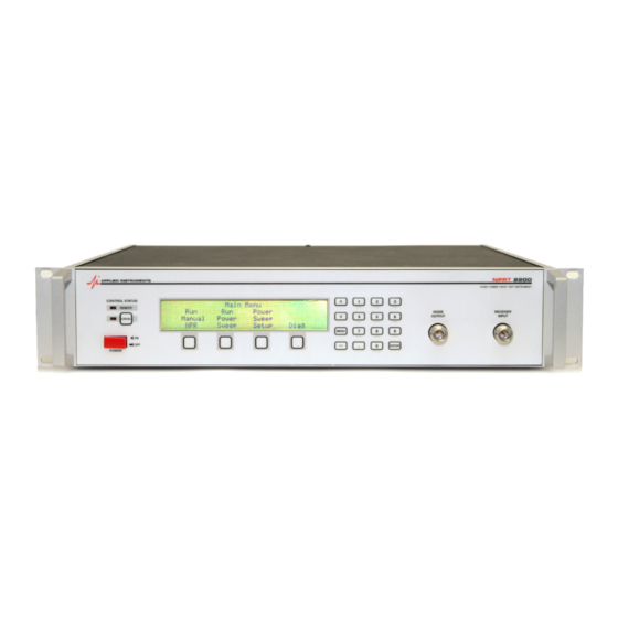
- Page 1 Operation Manual NPRT 2200 NPRT 2200 Operation Manual Module Version NPRT 2200 4.05 NprGraph 2.11 SwpEditor 2.00 12/02/2016...
-
Page 2: Table Of Contents
Operation Manual NPRT 2200 Table of Contents 1. Introduction......................1 1.1. NPR Measurement..................1 1.2. NPRT Block Diagram..................1 1.3. Power Sweep Graph..................2 2. Installation and Setup.....................3 2.1. Connections.....................3 2.2. Warm-up......................3 2.3. Software Installation..................3 3. Front Panel Operations..................4 3.1. Main Menu.......................4 3.2. User Calibration....................5 3.3. -
Page 3: Introduction
DUT may be any active RF component that operates in the frequency band of the instrument. The output from the DUT is measured by the receiver portion of the NPRT 2200, with and without the notch filter inserted into the input signal, and the NPR is calculated. -
Page 4: Power Sweep Graph
Operation Manual NPRT 2200 1.3. Power Sweep Graph In a Power Sweep test, the NPR is measured for a sequence of input power levels. Using a PC, this data can be plotted to characterize the performance of the DUT across its input power range. -
Page 5: Installation And Setup
2) Connect the DUT RF output to the NPRT 2200 “Receiver Input” port. 3) Connect your PC using either: a) PC serial port to the NPRT 2200 serial port on the back panel with the provided cable (or a standard straight-thru serial cable). -
Page 6: Front Panel Operations
NPRT 2200 3. Front Panel Operations The NPRT 2200 stand-alone operations are limited to single point NPR testing, source controls, calibration and diagnostics. Stand-alone power sweep tests may be available in a future version. Power Sweep tests are available with this version using the supplied PC software. -
Page 7: User Calibration
Operation Manual NPRT 2200 3.2. User Calibration The instrument is temperature compensated and calibrated at the factory to maintain accuracy over normal operating conditions. The calibration screen allows offsetting the measurements to allow for cable and connector loss between the instrument and the DUT. This procedure requires an external power meter capable of measuring a level of +5 dBm. - Page 8 Operation Manual NPRT 2200 Automatic TX Entry The automated procedure for the transmit side requires an external power meter. Connect the power meter to the end of the source cable, enter the power meter reading, and press NEXT. You will be prompted to enter a reading for each frequency band.
-
Page 9: Manual Operations
Operation Manual NPRT 2200 3.3. Manual Operations Press “Manual” from the main menu to display the following screen, which can be used to set individual source controls and display the measured power: MANUAL Range: 5:42 Power: Off Notch: 21.4 Source: -50.00... -
Page 10: Setup
Operation Manual NPRT 2200 When the test is complete the measured output power, noise power and NPR will be displayed: Manual NPR Input 10.0 dBm Enter Input Power Output 26.6 dBm Noise-32.4 dBm START EXIT NPR 59.0 dB 3.5. Setup... -
Page 11: Diagnostic Screens
Operation Manual NPRT 2200 4. Diagnostic Screens The diagnostic screens are intended for use in diagnosing possible problems with the instrument. These screens are not intended for use in normal operations. There are 3 screens, organized under a diagnostic menu screen around 3 major subsections of the device. -
Page 12: Filter Board Diagnostics
Operation Manual NPRT 2200 4.2. Filter Board Diagnostics This screen contains the diagnostics pertaining to the filter board. Filter Diag Range:1 Base: 10.36 32.5 Deg C Atten:3 NS-3:-27.08 0.02 Notch:0 Path:-43.48 EXIT Output:-60.20 You may specify: 1) The frequency range selection:... -
Page 13: Switch Diagnostics
Operation Manual NPRT 2200 a) 0 = no notch b) 1 = 21.4 MHz c) 2 = 30.5 MHz d) 3 = not available The system will display: 1) The temperature of the receiver 2) The measured A/D counts 3) The calibrated receiver measurement 4.4. -
Page 14: Computer Controlled Operation
NPRT 2200 5. Computer Controlled Operation The following Windows applications programs are available for use with the NPRT 2200: 1) NprGraph – provides a power sweeping function and graphs the results. 2) SwpEditor – edits the setup files that define the sweep function for NprGraph. -
Page 15: Swpeditor Screen
Operation Manual NPRT 2200 5.3. SwpEditor screen The table defines the steps used in the power sweep. The NprGraph program will process each segment definition line in turn by starting at the minimum power level, and repeatedly adding the step increment until the maximum level is reached. An NPR measurement is made at each step. -
Page 16: Power Sweep
Operation Manual NPRT 2200 5.5. Power Sweep To run a test, select the setup file you want from the drop down menu. The frequency range and notch frequency will default to the selections made in the setup file but you may change them if desired. -
Page 17: Power Sweep Graph
Operation Manual NPRT 2200 5.6. Power Sweep Graph At this point, the graph is complete and the pop-up dialogs are removed. You can now view and print the graph. The graph plots measured NPR by Input Power. The data points are shown as dots connected by green lines. -
Page 18: File Menu Options
Operation Manual NPRT 2200 If a “passing dynamic range” limit is entered, a PASS or FAIL grade is reported indicating if the dynamic range meets the limit. 5.7. File Menu Options The usual file menu options are available: File New – to start a new graph and access the Power Sweep dialog File Open –... -
Page 19: Edit Menu Options
Operation Manual NPRT 2200 5.9. Edit Menu Options The Edit sub-menu provides the following functions: Copy Copies the graph to the clipboard. Header Info To edit the header information first entered at the end of the test. Graph Setup To change the graph limits. - Page 20 Operation Manual NPRT 2200 Graph Setup The graph appearance may be altered using this dialog. Note: this dialog box is also available by right clicking on the graph. You may change the limits used for the X and Y axis.
-
Page 21: Nprt Menu Options
Manager and change the port to a lower number. Connect The “connect” function is for testing the serial port connection to the NPRT 2200. It just tries to read the serial number and version from the unit. 5.11. Batch Operation For automated testing, the NprGraph program can be run from a Windows DOS Command Prompt window. - Page 22 Operation Manual NPRT 2200 7. “/p” is optional and directs the program to automatically print the output to the default printer. 8. The command prompt window should be directed to the C:\Applied\ folder (or wherever NprGraph is installed) before running the command.
-
Page 23: Remote Commands
Operation Manual NPRT 2200 6. Remote Commands As demonstrated by the NprGraph software, the instrument may be controlled from a computer using an RS-232 serial or USB connection. The remote command interface is similar to the standard SCPI protocol although that standard is not completely supported. - Page 24 Operation Manual NPRT 2200 Freq:range:avail? 2, 5:42 MHz, 5:65 MHz Notch Filter Selection [SOURce:]NOTCH: FREQuency <value> [SOURce]:NOTCH:FREQuency? Where value is the notch frequency in MHz. If a notch is selected that is not installed, an error 100, “Invalid value” will be posted.
- Page 25 Operation Manual NPRT 2200 Measuring Level MEASure:LEVel? Measures the received power level at the presently selected range, notch and source power level. Measuring Carrier Level MEASure:CARrier? Removes the notch filter and measures the resulting carrier power level at the present source power settings.
-
Page 26: Error Reporting
-100, "Command error" -350, "Queue overflow" 6.4. SCPI Required Commands The following commands are implemented as required by the SCPI standard but have no real function in the NPRT 2200. *CLS Clear Status Command *ESE Standard Event Status Enable Command... -
Page 27: Multiple Commands
*TST? Self Test Query *WAI Wait to continue Command The NPRT 2200 has no overlapped commands so the *OPC, *WAI and *OPC commands are not needed. 6.5. Multiple Commands SCPI allows multiple commands to be strung together on the same line separated by semi- colons. -
Page 28: Upgrading Firmware
The installation procedure is similar to the installation of the NprGraph software. Once the FlashUpdate program is installed, connect your NPRT 2200 to the PC and start FlashUpdate. It will check our web site for the latest release and select the modified components for updating. - Page 29 Any application recommendation made by Applied Instruments for the use of its products are based upon tests believed to be reliable, but Applied Instruments makes no warranty of the results to be obtained. This warranty is in lieu of all other warranties, expressed or implied, and no representative or person is authorized to represent or assume for Applied Instruments any liability in connection with the sale of our products other than that set forth herein.
Need help?
Do you have a question about the NPRT 2200 and is the answer not in the manual?
Questions and answers