Table of Contents
Advertisement
Quick Links
METAL INDUSTRY VRANJE
st:Radnička n-1
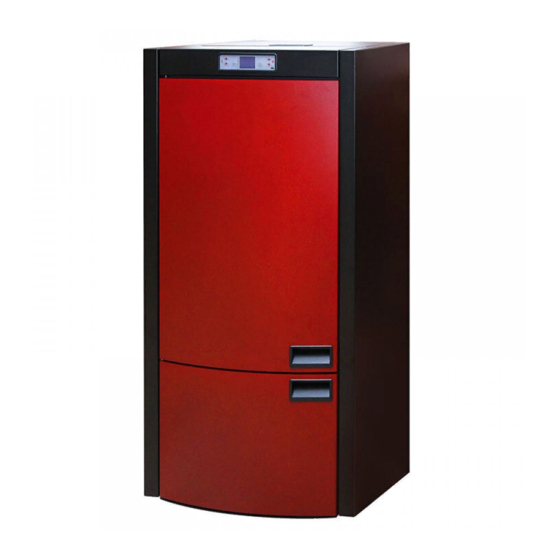
PELLET BOILER
COMMO COMPACT
Pellet → woody biomass → biofuel
INSTALLATION, OPERATION AND MAINTENANCE MANUAL
This product meets the requirements of the Ecodesign Directive in terms of efficiency and air pollution level, in order to
contribute to the reduction of energy consumption and negative environmental impact.
ENG - V.3 .0
1212006
Advertisement
Table of Contents

Related Manuals for alfaplam COMMO COMPACT


Summary of Contents for alfaplam COMMO COMPACT
- Page 1 METAL INDUSTRY VRANJE st:Radnička n-1 PELLET BOILER COMMO COMPACT Pellet → woody biomass → biofuel INSTALLATION, OPERATION AND MAINTENANCE MANUAL This product meets the requirements of the Ecodesign Directive in terms of efficiency and air pollution level, in order to contribute to the reduction of energy consumption and negative environmental impact.
- Page 2 The heating devices (hereinafter referred to as the “boilers”) of ALFA PLAM (hereinafter referred to as ALFA PLAM) are made and tested in accordance with the safety measures of the applicable regulations of the European Community. This Manual is intended for the boiler users, installers, operators and persons responsible for the maintenance of the boilers shown on the first page of the Manual.
- Page 3 18. Class of boiler according to EN 303-5:2012 19.The flue gas mass 12,99 g/s 20. Maximum output power 450 W 21. Voltage/frequency 230V/50Hz 22. Weight: -Net 230 kg -Gross 265 kg...
-
Page 4: Table Of Contents
Contents: THE PURPOSE OF THIS MANUAL ........................1 1.1. UPDATING .............................. 1 THE RESPONS IBILITY OF THE MANUFACTURER ..................1 2.1. THE BASIC CHARACTERISTICS OF THE USER..................1 2.2. THE TRANSPORTATION AND USE OF THE BOILER – HANDLING ............1 2.3. - Page 5 15.5. ALARMS ............................26 15.5.1. Smoke temperature probe alarm ....................26 15.5.2. Smoke temperature exceeding alarm ..................26 15.5.3. Ignition failure alarm ......................... 26 15.5.4. Alarm for fire extinguishing during work mode ................26 15.5.5. Alarm for screw feeder safety pressure stat ................27 15.5.6.
-
Page 6: The Purpose Of This Manual
1. THE PURPOSE OF THIS MANUAL The purpose of this Manual is to enable the user to take all necessary measures and prepare all necessary equipment and materials in order to ensure the safe and proper exploitation i.e. use of the boiler. 1.1. -
Page 7: The Installation - Incorporation Of The Boiler
When the installation is completed, the system must be put into a trial operation for at least 30 minutes in order to check up all the packing and seals of the system. When the incorporation and significant details are completed, the installer is obliged to provide the client with the following: −... -
Page 8: Instructions For Combustion And Ventilation
First, it should be ensured that there is sufficient combustion air in the room where the boiler is located. Occasional inspection is recommended to ensure that combustion air is properly supplied to the biofuel combustion chamber. The boiler operates on 230 V – 50 Hz. Ensure that the electric cable is not entangled under the boiler, that it is away from hot places and that it cannot come in contact with any sharp edge that could cut it. - Page 9 C) Seal D) Inspection – control opening. Flue pipes in bad condition or made of inappropriate material (asbestos cement, galvanized sheet metal, etc. with coarse and rough or porous surfaces) are illegitimate and they jeopardize and hamper the proper operation of the boiler. Smoke can be discharged through a classic flue pipe (see the figures below) provided that the following regulations are met: −...
- Page 10 Figure 3 AISI 316 steel chimney with double insulated chamber, Fireproof chimney with double insulated chamber and an made of material resistant to 400°C. Optimal efficiency outer lining of lightweight concrete. 100% Optimal efficiency 100% Traditional clay chimney with recesses. Optimal efficiency It is forbidden to use chimney pipes that have a rectangular internal cross-section with a ratio that differs from the plan.
-
Page 11: The Insulation And Diameter Of The Openings (Holes) On The Roof (Or On The Wall)
Chimney - positioning and distance 3.4. THE INSULATION and DIAMETER OF THE OPENING S (Holes) ON THE ROOF (or on the Wall) Once the position of the boiler is determined, it is necessary to make a hole i.e. an opening the flue pipe should pass through. - Page 12 Ø100 Ø80 Figure 6 1. T-shaped pipe fittings – T-shaped pipe coupling 2. Cleaning direction 3. Opening, window for servicing / inspection 4. Cleaning direction 5. T-shaped pipe fittings – T-shaped pipe coupling 6. Cleaning direction 7. Sealed cover for the purpose of cleaning (plug) direction SMER DIMA...
-
Page 13: The Intake Of Combustion Air (Figure 8)
Insulation thickness D.80 D.100 Diameters of holes (openings) that should be made (mm) Walls made of wood or combustible anyway, or parts that are combustible Concrete wall or roof Brick wall or roof Table 2: Insulation thickness for the part of the system that passes through wall or roof First of all, it is necessary to provide PERFECT CIRCULATION of air (draught) in the flue pipe which must be free of any obstacles such as narrowing or angles. -
Page 14: Connection To The Electric Power Supply
horizontally from 0.3 m above away from smoke outlet Table 4: Minimum distances for the intakes of combustion air 3.6. CONNECTION TO THE ELECTRIC POWER SUPPLY These boilers should be connected to the electric power supply. Our boilers have electric cables suitable for medium temperatures. -
Page 15: Warning Of The Safety Measures For The User
function. − Do not make any modifications for whatever reason except those allowed and explained by the manufacturer. − Always use original spare parts. Never allow the components to completely wear out before you replace them. Replacing a worn out part i.e. component of the boiler before it breaks down contributes to the prevention of injuries caused by an accident due to a sudden breakdown i.e. - Page 16 firebox should be taken out for ensuring that there is no excessive ash accumulated at the bottom of the firebox. Then place the firebox back in its place, making it stable, to ensure the safe operation of the boiler. If you have any doubts, please do not hesitate to call the authorized service centre for further information and clarification, as the manufacturer does not have any insight into the installation of the boiler and does not offer any warranty for the incorporation of the boiler and its maintenance.
- Page 17 Figure 14 Figure 15 -LOWER SMOKE CHAMBER It should be cleaned manually at each consumed 90-100 kg of pellets (two full tanks). Raise the cover of the pellet tank. In the tank, in the front upper part, under the cover, there is a button for the mechanism for cleaning the chamber. By pulling the button for the mechanism few times forward-backward, you will clean the chamber.
-
Page 18: Cleaning And Maintenance (For Maintenance Workers)
The boiler and ash must be completely cool – unplug the power cable of the boiler. At the end of the heating season, unplug the power cable of the boiler for safety reasons. It is very important to clean and check the boiler as it is explained above. -
Page 19: Fuel Pellet Storage
Under no circumstances shall the manufacturer be responsible for the poor operation of the boiler due to the use of poor quality pellets. If sawdust or small – decomposed pellets are put into the funnel-shaped part of the boiler i.e. the fuel tank, these may block the pellet feeding. -
Page 20: Pressure Line And Return Duct
Legend: 1. Pellet boiler 2. Hydraulic crossover 3. Circulation pump 4. Non-return valve 5. Three-way mixing valve with fitting thermostat 6. Circulation pump 7. Underfloor heating separator 8. Non-return valve IMPORTANT! -Connection of the furnace to the hydraulic installation can be performed by qualified technician ONLY, and in accordance with the present legislation of the country in which the installation is performed. -
Page 21: Furnace Built-In Components
Put thermo manometer on pressure line that will show water pressure in the system and water temperature on the boiler outlet. 11. FURNACE BUILT-IN COMPONENTS -Furnace has following built-in components: -safety valve, -circulating pump, -automatic air vent valve, -expansion tank and -fill and drain cock. -
Page 22: Description And Functioning Of The Furnace Operation Controller
-Never remove the safety grill from the reservoir. During pellet filling, make sure that the pellet bag does not get in touch with hot surfaces. 15. DESCRIPTION AND FUNCTIONING OF THE FURNACE OPERATION CONTROLLER 15.1. USER INTERFACE The display unit enables communication with the controller by simple pressing on certain buttons. 15 .1 .1. -
Page 23: Operation Mode (User)
Increasing power SETTINGS Moves on to the previous submenu, set modulations are memorised Table 5 15.2. OPERATION MODE ( USER) 15 .2 .1. St ov e ig ni ti on When the stove is connected to power supply, you should turn the switch which is at the back side of the stove to position 1. -
Page 24: Failed Ignition
Figure 28 15 .2 .2. Fa i l ed ig ni ti on Once a period of 20 minutes runs out, if the temperature of smoke did not reach the minimally allowed value of 45ºC, the stove transfers to the state of an alarm, see point 15.6.3. 15 .2 .3. -
Page 25: Cleaning Of The Boiler
which means setting the output power. With button 6 we increase and with button 5 we reduce the power of the stove. Level 1 is minimal and level 5 is maximal power. Figure 32 15 .2 .7. Cl ea n in g o f th e bo il e r During normal operational mode, "BOILER CLEANING"... -
Page 26: Menu 02 - Programming Of The Stove Operation
Figure 35 Press the button SET and the buttons 1 or 2 to set the exact day in the week (MONDAY, TUESDAY...) (figure 36) Press the button SET and the buttons 1 and 2 to set the clock time (figure 37). Figure 36 Figure 37 Press the button SET and the buttons 1 and 2 to set the minutes (figure 38). - Page 27 There are three types of programming of the stove operation: Daily programming Weekly programming Weekend programming Daily programming This enables setting of the daily functions of the chronothermostat. The stove can be ignited and switched off twice as desired and this is regulated by programming, having in mind that sufficient time is required between the switching off and the new ignition so that the stove could cool.
- Page 28 Figure 48 Figure 49 By pressing the button SET, a transition is made towards setting of another program. With the button 1 we adjust the time of ignition of the stove (figure 49). By pressing the button SET we set the time of switching off of the stove (figure 50). After the terminated setting, with the button 4 we return to the basic menu and an indicator will appear on the display that the programming is active.
- Page 29 Figure 54 By pressing the button SET and the button 1 we activate (ON) or deactivate (OFF) the program 1 for the corresponding day in the week starting from Monday, up to Sunday as shown in figures 55 and 56. The transition from day to day is performed by pressing the button SET.
-
Page 30: Menu 03 - Language Selection
Figure 60 The same procedure is applied for programming of another weekend program, figure 61 and 62. Figure 61 Figure 62 After these adjustments, we return to the main menu by pressing the button 4. SUGESTION: to avoid confusion and unwanted turning on and off, activate only one program if you are not sure what do you want to accomplish. -
Page 31: Alarms
Access to this menu is not available to the User. 15.5. ALARMS In case of malfunction, controller turns on and warns for irregularities with different kinds of alarms. Following alarms are envisaged: Source of alarm Display message Smoke temperature probe PROBE EXHAUST Smoke temperature exceeding HOT EXHAUST... -
Page 32: Alarm For Screw Feeder Safety Pressure Stat
Figure 66 Shutdown procedure immediately starts. 15 .5 .5. Ala rm fo r sc r e w f e ed e r sa fe t y p r ess ur e sta t If pressure stat (air input meter) detects that pressure value is below activation threshold, pressure stat stops screw feeder power supply. - Page 33 < 30 sec Pellet filling < 30 sec Pellet filling Waiting for flames < 30 sec Waiting for flames Work < 30 sec Work Boiler cleaning < 30 sec Boiler cleaning < 30 sec Table 7 In all cases when duration of power outage was longer than 30 seconds, furnace shuts down. When AC power is on again (the power outage was longer than 30 seconds) then the following is shown in the display (figure 69): Figure 72 Figure 73...
-
Page 34: Connection Scheme
16. CONNECTION SCHEME Bellow is given a typical connection scheme. Figure 75 17. SECURITY MEASURES Furnace is equipped with following safety devices: -PRESSURE REGULATOR Controls the pressure in the chimney. It stops transport spiral for the pellet when the outlet is clogged or when it faces pressure (draught) -FLUE GASES TEMPERATURE SENSOR Measures the temperature of the flue gasses and allows furnace ignition o stops it if the flue gasses temperature goes... -
Page 35: Malfunction - Causes - Solutions
-NO IGNITION If during ignition there is no flame, furnace automatically changes to alarm status. 18. MALFUNCTION - CAUSES - SOLUTIONS PROBLEMS POSSIBLE CAUSES SOLUTIONS Wood pellets are not in 1. Wood pellet reservoir is empty. 1. Fill the reservoir. the firebox, in combustion 2. -
Page 36: Information On The Disposal (Discarding) And Disassembly (Dismantling) Of The Boiler
19. INFORMATION ON THE DISPOSAL (DISCARDING) AND DISASSEMBLY (DISMANTLING) OF THE BOILER The disassembly and disposal of (an old, used) boiler is the sole responsibility of the owner of the boiler. The owner of the boiler must observe the applicable legal regulations of his own country related to the safety and protection of the environment.
Need help?
Do you have a question about the COMMO COMPACT and is the answer not in the manual?
Questions and answers