Table of Contents
Advertisement
2-342-216-91(1)
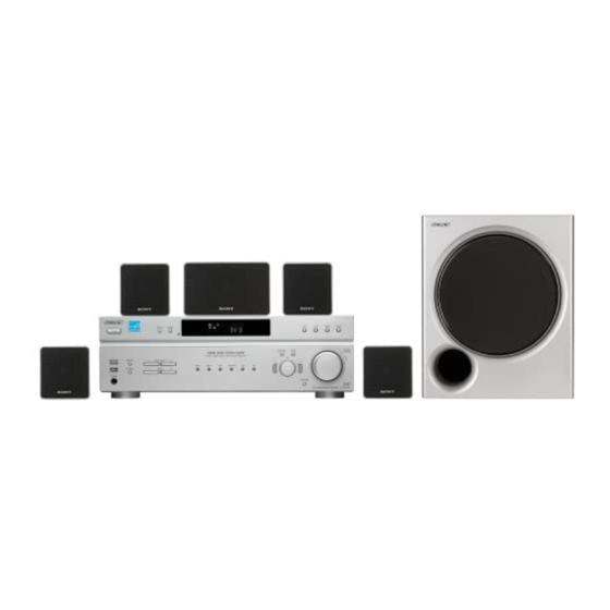
Home Theatre
System
Operating Instructions
Owner's Record
The model and serial numbers are located on the rear of the unit. Record the serial
number in the space provided below. Refer to them whenever you call upon your
Sony dealer regarding this product.
Model No.
Serial No.
HT-DDW670T
©2005 Sony Corporation
Advertisement
Table of Contents
Troubleshooting

Related Manuals for Sony HT-DDW670T


Summary of Contents for Sony HT-DDW670T
-
Page 1: Operating Instructions
Owner’s Record The model and serial numbers are located on the rear of the unit. Record the serial number in the space provided below. Refer to them whenever you call upon your Sony dealer regarding this product. Model No. Serial No. - Page 2 For customers in the United States ® is a U.S. registered NERGY mark. As an E NERGY Sony Corporation has determined that this product meets the E guidelines for energy efficiency. ® partner, ® NERGY...
-
Page 3: About This Manual
About This Manual • The instructions in this manual are for model HT-DDW670T. Check your receiver’s model number by looking at the lower right corner of the front panel. • The instructions in this manual describe the controls on the receiver. You can also use the controls on the supplied remote if they have the same or similar names as those on the receiver. -
Page 4: Table Of Contents
Table of Contents Getting Started 1: Check how to hookup your components... 5 1a: Connecting components with digital audio output jacks ... 7 1b: Connecting components with only analog audio jacks ... 9 2: Connecting the antennas ... 10 3: Connecting speakers ... 11 4: Connecting the AC power cord ... -
Page 5: 1: Check How To Hookup Your Components
Getting Started 1: Check how to hookup your components Steps 1a through 1b beginning on page 7 describe how to hook up your components to this receiver. Before you begin, refer to “Connectable components” below for the pages which describe how to connect each component. -
Page 6: Required Cords
Required cords The hookup diagrams on the subsequent pages assume the use of the following optional connection cords (A to C) (not supplied unless indicated). A Audio cord White (L) Red (R) B Optical digital cord Notes • Turn off the power to all components before making any connections. •... -
Page 7: 1A: Connecting Components With Digital Audio Output Jacks
1a: Connecting components with digital audio output jacks Hooking up a DVD player For details on the required cords (A OUTPUT DIGITAL COAXIAL DIGITAL OPTICAL SA-CD/ DVD IN COAXIAL C), see page 6. – DVD player OUTPUT AUDIO ANTENNA AUDIO AUDIO IN AUDIO IN AUDIO IN... - Page 8 Hooking up a Super Audio CD/CD player For details on the required cords (A OPTICAL SA-CD/ DVD IN COAXIAL DIGITAL OPTICAL All the digital audio jacks are compatible with 32 kHz, 44.1 kHz, 48 kHz and 96 kHz sampling frequencies. Note The sound is not output when you play a Super Audio CD on the Super Audio CD player connected to the SA-CD/CD OPTICAL IN jack on this receiver.
-
Page 9: 1B: Connecting Components With Only Analog Audio Jacks
1b: Connecting components with only analog audio jacks For details on the required cords (A DVD player OUTPUT AUDIO DIGITAL OPTICAL SA-CD/ DVD IN COAXIAL Super Audio CD/CD C), see page 6. – Satellite Tuner or VCR OUTPUT AUDIO ANTENNA AUDIO AUDIO IN AUDIO IN... -
Page 10: 2: Connecting The Antennas
2: Connecting the antennas Connect the supplied AM loop antenna and FM wire antenna. DIGITAL OPTICAL SA-CD/ DVD IN COAXIAL The shape of the connector varies depending on the area code. Notes • To prevent noise pickup, keep the AM loop antenna away from the receiver and other components. •... -
Page 11: 3: Connecting Speakers
3: Connecting speakers Connect your speakers to the receiver. This receiver allows you to use a 5.1 channel speaker system. To fully enjoy theater-like multi channel surround sound requires five speakers (two front speakers, a center speaker, and two surround speakers) and a sub woofer (5.1 channel). Example of 5.1 channel speaker system configuration Center speaker Front speaker (Left) - Page 12 Required cords A Speaker cords (supplied) (–) Center speaker AUDIO WOOFER Sub woofer * If you have an additional active subwoofer, connect it to SUB WOOFER AUDIO OUT jack. B Monaural audio cord (not supplied) Black Front speaker Front speaker (Right) WOOFER SURROUND...
- Page 13 Attaching the front speakers base Before connecting the front speakers, attach it to the supplied base. Note Spread a cloth on the floor to avoid damaging the floor. Remove the front speaker with the cushion from the carton. Place TOP cushion and the top portion of the speaker on the floor as shown below.
-
Page 14: Installing The Speakers On The Wall
• Contact a screw shop or installer regarding the wall material or screws to be used. • Sony is not responsible for accident or damage caused by improper installation, insufficient wall strength or improper screw installation, natural calamity, etc. -
Page 15: 4: Connecting The Ac Power Cord
4: Connecting the AC power cord Setting the voltage selector If your receiver has a voltage selector on the rear panel, check that the voltage selector is set to the local power supply voltage. If not, use a screwdriver to set the selector to the correct position before connecting the AC power cord to a wall outlet. -
Page 16: 5: Setting Up The Speakers
5: Setting up the speakers You can use the SET UP menu to set the distance and location of the speakers connected to this receiver. Press ?/1 to turn on the receiver. Press MAIN MENU repeatedly to select “ SET UP ”. Press repeatedly to select the parameter you want to adjust. - Page 17 The receiver lets you to input the speaker position in terms of distance. However, it is not possible to set the center speaker further than the front speakers. Also, the center speaker cannot be set more than 1.5 meters (5 feet) closer than the front speakers. Likewise, the surround speakers cannot be set further away from the listening position than the front speakers.
-
Page 18: 6: Adjusting The Speaker Levels And Balance
6: Adjusting the speaker levels and balance — TEST TONE Adjust the speaker levels and balance while listening to the test tone from your listening position. Use the remote for the operation. The receiver employs a test tone with a frequency centered at 800 Hz. -
Page 19: Amplifier Operation
Amplifier Operation Selecting the component Press input buttons to select the input. To select the Press VIDEO 1 or VIDEO 2 Satellite tuner VIDEO 2 DVD player Super Audio CD or SA-CD/CD CD player Built-in tuner (FM/AM) FM or AM The selected input appears in the display. -
Page 20: Listening To Fm/Am Radio
Listening to FM/AM radio You can listen to FM and AM broadcasts through the built-in tuner. Before operation, make sure you have connected the FM and AM antennas to the receiver (see page 10). The tuning scale is: FM: 100 kHz AM: 10 kHz* * The AM tuning scale can be changed (see page 39). -
Page 21: Presetting Radio Stations
Presetting radio stations You can preset up to 30 FM or AM stations. Then you can easily tune in the stations you often listen to. Presetting radio stations Press FM or AM to select the FM or AM band. The last received station is tuned in. Tune in the station that you want to preset using Automatic Tuning (page 20) or Direct Tuning (page 20). -
Page 22: Changing The Display
Changing the display Changing the information in the display You can check the sound field etc. by changing the information in the display. Press DISPLAY repeatedly. Each time you press DISPLAY, the display will change cyclically as follows. Index name of the input Sound field currently applied When the tuner is selected t Frequency t Sound... -
Page 23: About The Indications In The Display
About the indications in the display DIGITAL SLEEP OPT COAX SL S SR A SW: Lights up when audio signal is output from the SUB WOOFER jack. B LFE: Lights up when the disc being played back contains the LFE (Low Frequency Effect) channel and the LFE channel signal is actually being reproduced. -
Page 24: Enjoying Surround Sound
Enjoying Surround Sound Using only the front speakers and sub woofer — 2CH STEREO In this mode, the receiver outputs the sound from the front left/right speakers and sub woofer. When multi channel surround formats are input, the signals are downmixed to 2 channel with bass frequencies being output from the sub woofer. -
Page 25: Selecting A Sound Field
Sound fields with marks use DCS technology. DCS is the concept name of the surround technology for home theater developed by Sony. DCS uses the DSP (Digital Signal Processor) technology to reproduce the sound characteristics of an actual cinema cutting studio in Hollywood. - Page 26 C.ST.EX C (CINEMA STUDIO EX C) Reproduces the sound characteristics of the Sony Pictures Entertainment scoring stage. This mode is ideal for watching musicals or films where orchestra music is featured in the soundtrack. About CINEMA STUDIO EX modes CINEMA STUDIO EX modes are suitable for watching motion picture DVDs (etc.), with...
-
Page 27: Advanced Adjustments And Settings
Advanced Adjustments and Settings Switching the audio input mode for digital components — INPUT MODE You can switch the audio input mode for components which have digital audio input jacks. Press input buttons to select the input. Press INPUT MODE repeatedly to select the audio input mode. -
Page 28: Resetting Sound Fields To The Initial Settings
x CTR XXX dB (Center speaker level) x SUR.L. XXX dB (Surround speaker (left) level) x SUR.R. XXX dB (Surround speaker (right) level) x S.W. XXX dB (Sub woofer level) Initial setting: 0 dB You can adjust from –10 dB to +10 dB in 1 dB steps. COMP. -
Page 29: Adjusting The Tone
Adjusting the tone You can adjust the tonal quality (bass, treble level) of the front speakers using the TONE menu. Start playing a source encoded with multi channel surround effects (DVD, etc.). Press MAIN MENU repeatedly to select “ TONE ”. Press repeatedly to select the parameter you want to adjust. - Page 30 x DEC. XXXX (Digital audio input decoding priority) Lets you specify the input mode for the digital signal input to the DIGITAL IN jacks. • AUTO Automatically switches the input mode between DTS, Dolby Digital, or PCM. • PCM PCM signals are given priority (to prevent the interruption when playback starts).
-
Page 31: Other Operations
Other Operations Naming preset stations and inputs You can enter a name of up to 8 characters for preset stations and inputs selected with input buttons, and display it in the receiver’s display. To index a preset station Press FM or AM to select the FM or AM band, then tune in the preset station you want to create an index name for (page 21). -
Page 32: Operations Using The Remote Rm-Aau002
Operations Using the Remote RM-AAU002 You can use the remote RM-AAU002 to operate the components in your system. Before you use your remote Inserting batteries into the remote Insert R6 (size-AA) batteries with the + and – properly oriented in the battery compartment. When using the remote, point it at the remote sensor on the receiver. - Page 33 The tables below show the settings of each button. Remote Operations Function Button A.F.D. ef Receiver Selects the decoding mode for audio sound. ANGLE DVD player Selects viewing angle or changes the angles. ANT 0 VCR/ Selects output signal Satellite tuner from the antenna terminal: TV signal or VCR program.
- Page 34 0/10 es function and the duration which the receiver turns off automatically. Changes the subtitles. Turns off the receiver and other Sony audio/ video components. 2CH ed Outputs test tone. >10 ea Displays DVD title. -/-- ea To listen to radio programs.
-
Page 35: Changing The Factory Setting Of An Input Button
DSS (Digital Satellite Receiver) DCS (Digital CS Tuner) BSD (Digital BS Tuner) *Sony VCRs are operated with a VTR 2 or 3 setting. These correspond to 8 mm and VHS respectively. Now you can use the DVD button to control the CD player. -
Page 36: Additional Information
Do not use any type of abrasive pad, scouring powder or solvent such as alcohol or benzine. If you have any question or problem concerning your receiver, please consult your nearest Sony dealer. -
Page 37: Troubleshooting
Troubleshooting If you experience any of the following difficulties while using the receiver, use this troubleshooting guide to help you remedy the problem. There is no sound or only a very low-level sound no matter which component is selected. • Check that the speakers and components are connected securely and correctly. -
Page 38: Troubleshooting Guide
If the problem persist Consult your nearest Sony dealer. Reference sections for clearing the receiver’s memory To clear All memorized settings... -
Page 39: Specifications
Specifications AUDIO POWER SPECIFICATIONS POWER OUTPUT AND TOTAL HARMONIC DISTORTION: With 6 ohm loads, both channels driven, from 120 – 20,000 Hz; rated 60 watts per channel minimum RMS power, with no more than 0.7% total harmonic distortion from 250 milliwatts to rated output. - Page 40 Speaker section Front speakers (SS-MSP607) Center speaker (SS-CNP607) Surround speakers (SS-MSP607B) Front/center speakers Full range, magnetically shielded Surround speakers Full range Speaker units Front speakers 70 mm cone type Center/surround speakers 57 mm cone type Enclosure type Bass reflex Rated Impedance 6 ohms Dimension (w/h/d) (Approx.) Front speakers...
-
Page 41: List Of Button Locations And Reference Pages
List of button locations and reference pages How to use this page Use this page to find the location of buttons that are mentioned in the text. Main unit ALPHABETICAL ORDER A - H A.F.D. 9 (24, 25, 26) AM qh (19, 20, 31, 39) DIMMER 3 (22) DISPLAY 2 (22, 38) Display 5 (22) -
Page 42: Index
Index Adjusting CUSTOMIZE parameters 29 LEVEL parameters 27 SET UP parameters 16 speaker levels and balance 18 TONE parameters 29 Automatic tuning 20 Changing display 22 Clearing receiver’s memory 15 CUSTOMIZE menu 29 Digital Cinema Sound 25 Direct tuning 20 Dual Mono 30 Indexing. - Page 44 Sony Corporation Printed in Malaysia...
Need help?
Do you have a question about the HT-DDW670T and is the answer not in the manual?
Questions and answers