
Related Manuals for Sunred LH15


Summary of Contents for Sunred LH15
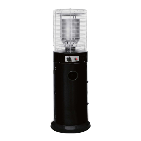
- Page 1 Manual Lounge heater (EN) Handleiding Lounge heater (NL) Handbuch Lounge heizung (DE) Manual Lounge au gaz (FR) LH15 LH15 Lounge heater www.sunred.nl...
- Page 2 Lounge Heater EN User instructions - please keep for future references TECHNISCHE SPECIFICATIES Wa age: 10.000 Wa s 10.000 W Element type: Gas cates: CE, Dimensions: H132cm H132cm All measurements are approximate www.sunred.nl...
- Page 3 WARNlNG SAFETY RULES PLEASE READ THE FOLLOWING SAFETY RULES PRlOR TO OPERATION OF THE HEATER If you smell gas: 1 Shut off gas to the appliance. 2 Extinguish any open flame. 3 If odor continues, immediately call your gas supplier or your fire Department.
- Page 4 warning -This appliance must be installed and the gas cylinder stored in accordance with the regulations in force; -Do not obstruct the ventilation holes of the cylinder housing; -Do not move the appliance when in operation; -Shut off the valve at the gas cylinder or the regulator before moving the appliance; -The tubing or the flexible hose must be changed within the prescribed intervals;...
-
Page 5: Table Of Contents
TABLE OF CONTENTS Caution ………………………………………………………. Heater Stand and Location ………………………………… Gas Requirements ………………………………………….. Leakage Test ………………………………………………… Operation and Storage ……………………………………... Cleaning and Care ………………………………………….. Parts and Specifications ..………………………………….. Assembly Parts and Procedures ………………………….. Problems Check List ………………………………………... -
Page 6: Caution
The heater does not reach temperature. The burner makes popping noise during use (a slight noise is normal when the burner is ex nguished). Smell of gas in conjunction with extreme yellow ping of the burner flames. www.sunred.nl... - Page 7 Read the instruc ons before using this appliance. The appliance must be installed in accordance with the instruc ons and local regu ons. For connec on of hose and regulator,and connec on of regulator and hose, please refer to photo sho wed above. www.sunred.nl...
-
Page 8: Heater Stand And Location
Make sure the safety control valve is in the OFF posi on. Turn the gas supply ON. In case of a leak, turn off the gas supply. Tighten any leaking fi ings, then turn the gas supply on and re- check. Never leak test while smoking. www.sunred.nl... -
Page 9: Operation And Storage
Warning check that no broken on the glass is found before opera on. 1. Fully close gas valve. 2. Turn control knob clockwise to OFF posi on. Off: the heater stop work Hi: maximum temperature posi on Lo: minimum Variable control knob temperature posi on Pointer regulator www.sunred.nl... -
Page 10: Cleaning And Care
Remove debris from the burner to keep it clean and safe for use. Cover the burner unit with the optional protective cover when the heater is not in use. PARTS AND SPECIFICATIONS 360 mm Protection guard Head assembly Tank Door Base 460 mm www.sunred.nl... - Page 11 1. 55on the injector indicates that the size of injector is 1.55 mm 1. 55o 1.55 m The hose and regulator assembly must conform to local standard codes. Regulator outlet pressure should meet the corresponding appliance category in B. on. The appliance requires approved hose in 0,6 m length. www.sunred.nl...
-
Page 12: Assembly Parts And Procedures
ASSEMBLY PARTS During periods of extended inactivity or when transporting: Turn the control to “OFF” position. Disconnect LPG cylinder and move to a secure, well-ventilated location outdoors. DO NOT store in a location that will exceed 50 degrees C. Store heater upright in an area sheltered away from weather conditions (such as rain, sleet, hail, snow) If desired, cover heater to protect exterior surfaces and to help prevent dust and debris collecting in air passages. - Page 13 ASSEMBLY PROCEDURES Attach wheel assembly (P) to base (O). Line up holes in wheel bracket with corresponding holes in base, insert two bolts M8 x 15 (BB)through holes, and finger tighten two M8 flange nuts (AA) is parallel to the base, and fully tighten bolts. Hardware Used M8 Flange Nut M8 x 15 mm...
- Page 14 3. Assembly of groupware of burner unit. Attach the housing lid onto the top of tank housing. Make sure the holes on the lid are corresponded to the holes on the housing. Insert 3 M5X10(MM) bolts to the holes and hand tighten by 3 flange nut M5 (NN) make sure the lid assembly is parallel to the base.
- Page 15 5. Attach regulator to gas line and tank 5.1 Fit the gas regulator rubber hose with the end thread of inlet gas steel pipe and tighten the nut. 5.2 Connect the regulator with the LPG gas tank In counter-clockwise direction and tighten it b y adjustable wrench.
- Page 16 6. Leak Check. WARNING! of the gas system is replaced. Never use an open flame to check for gas leaks. Be certain no sparks or open flames are WARNING! in the area while you check for leaks. Sparks or open flames will result in a fire or explosion, damage to property, serious bodily injury, or death.
-
Page 17: Problems Check List
PROBLEMS CHECK LIST PROBLEM PROBABLE CAUSE SOLUTION Pilot will not light Gas valve may be OFF Turn the gas valve ON Tank fuel empty Refill LPG tank Opening blocked Clean or replace opening Air in supply system Purge air from lines Loose connec ons Check all Pilot will not stay on... - Page 18 Lounge Heater NL Gebruikershandleiding – Bewaar voor eventueel toekomstig gebruik Technische Sp ca es Wa age: 10.000 Wa 10.000 Element type: Gas caten: CE Afme ng: H132cm H132c BELANGRIJK – Verwijder zorgvuldig de verpakking voor gebruik, maar bewaar de veiligheidsinstruc es. Deze ins es maken deel uit van het product.
- Page 19 GEBRUIKSAANWIJZING Bewaar de instructies voor toekomstig gebruik BELANGRIJK: VEILIGHEIDSVOORSCHRIFTEN Lees de veiligheidsvoorschriften voor u de heater in gebruik neemt VOOR UW VEILIGHEID Als u gas ruikt: 1. Sluit de gastoevoer naar het toestel. 2. Doof eventueel open vuur. 3. Als geur blijft, bel dan onmiddellijk uw gasleverancier of de brandweer. VOOR UW VEILIGHEID 1.
- Page 20 INHOUDSOPGAVE Waarschuwing Plaatsing van de heater Gasgebruik Lektest Gebruik en opslag Reiniging en onderhoud Onderdelen en specificaties Montage: Onderdelen en stappen Checklist bij storing...
- Page 21 WAARSCHUWING LEES DEZE VEILIGHEIDSVOORSCHRIFTEN VOOR GEBRUIK ZORGVULDIG DOOR. Gebruik de heater niet binnenshuis; dit kan persoonlijk letsel of materiële schade veroorzaken. Deze heater mag niet in/op recreatieve voertuigen en /of boten worden geïnstalleerd. Installatie en reparatie moet worden uitgevoerd door een gekwalificeerd persoon. Onjuiste installatie, aanpassing of wijziging kan persoonlijk letsel of materiële schade veroorzaken.
- Page 22 en controleert u het toestel voor hernieuwd gebruik. Controleer de slang minimaal een maal per maand, en telkens bij vervanging van de gasfles, of wanneer het apparaat d lang niet gebruikt is. Als de slang barstjes, scheurtjes of andere afwijkingen vertoont, dient deze te worden vervangen door een slang met dezelfde lengte en gelijkwaardige kwaliteit.
- Page 23 GEBRUIK EN OPSLAG De heater aanzetten Druk de controleschakelaar in en draai deze met de klok mee in de OFF-stand. Draai het ventiel van de gasfles volledig open. Druk de controleschakelaar in en draai deze tegen de klok in in de IGNITE-stand, daarna in de PILOT-stand (u hoort tweemaal een ‘klik’).
- Page 24 • Verwijder vuil van de brander om deze schoon en veilig voor gebruik te houden. • Bedek de brander met de optionele beschermkap als de heater niet in gebruik is. 360 mm ONDERDELEN EN SPECIFICATIES Vlammenscherm Branderunit Bedieningsunit Behuizing Bodemplaat Protection guard Head assembly Tank Door Base 460 mm www.sunred.nl...
- Page 25 Warmteafgi e via re A. Speci ca es Gebruik uitsluitend propaan, butaan of mengsels van deze gassen. Max. wa age: 10000 w : 10000 Min. wa age: 5000 w Verbruik: I 3B/P(30) I 3+(28-30/37) I 3B/P(50) I 3B/P(37) APPLIANCE CATEGORY: Butane, propane Butane, propane Butane, propane...
- Page 26 Montage instructies Montage onderdelen ONDERDELEN EN SPECIFICATIES Vlammenscherm Branderunit Bedieningsunit Behuizing Bodemplaat Flange Bolt M8 X 15 Qty. 5 Protection guard Qty. 2 Head assembly Tank Flange Screw M5 X 10 Qty. 5 Qty. 3 Door Wrench Base Qty. 1 Kleine onderdelen (weergegeven op ware grootte): Bout M8x15...
- Page 27 MONTAGE: STAPPEN Stap 1: Bevestig de wieltjes aan de bodemplaat met behulp van twee bouten M8x15 en twee moeren M8. Hardware Used M8 Flange Nut M8 x 15 mm Bolts Stap 2: Bevestig de behuizing aan de bodemplaat met drie schroeven M8x15 Hardware Used M8 x 15 mm...
- Page 28 Stap 3: Bevestig de branderunit aan de behuizing met drie schroeven M5x10 en 3x M5Moeren Hardware Used Screw M5 X 10 4-1. Gebruik 2 stuks M5x10 schroeven om het handvat te bevestigen aan de heater. 4-2. Hardware Used Screw M5 X 10...
- Page 29 Stap 5.1 Uitsluitend propaan. 5.2 Zorg voor een juiste aansluiting van de slang. Waarschuwing: Let op dat de slang niet in aanraking komt met hete oppervlakken. De slang kan smelten en daardoor gaan lekken en brand veroorzaken. Zet de gasfles stevig vast met behulp van de band. 5.2 Sluit de regelaar aan op de LPG-tank In tegengestelde richting en draai deze vast Met een verstelbare sleutel.
- Page 30 Stap 6: Lektest uitvoeren. Waarschuwing: Lektest moet jaarlijks worden uitgevoerd, of telkens wanneer een gas aangesloten wordt of een deel van het gassysteem vervangen wordt. Waarschuwing: Gebruik nooit een open vlam om een lektest uit te voeren. Zorg ervoor dat er geen vonken of open vlammen in de buurt zijn wanneer u een lektest uitvoert.
- Page 31 CHECKLIST BIJ STORING PROBLEEM MOGELIJKE OORZAAK OPLOSSING Waakvlam ontvlamt niet Gasventiel is dicht Draai het gasventiel open Gasfles leeg Gasfles bijvullen Opening geblokkeerd Schoonmaken of vervangen Lucht in aanvoersysteem Laat lucht ontsnappen Losse verbindingen Controleer verbindingen Waakvlam blijft niet aan Vuil rond waakvlam Schoonmaken Losse verbindingen...
- Page 32 Lounge heizung DE Bedienungsanleitung - Bitte bewahren Sie diese für zukünftige Verwendung TECHNISCHE SPEZIFIKATION Stromversorgung: 10.000 Wa 10.000 Element type: Gas kate: CE, Abmessungen: H132cm : H132cm All measurements are approximate WICHTIG - En ernen Sie vorsich g Verpackung vor dem Gebrauch, aber behalten Sie die Sicherheitshinweise. Diese Anweisungen sind Teil des Produkts.
- Page 33 Dieses Produkt ist nur für den Hausgebrauch und soll nicht kommerziell oder für Vertrag Zwecke verwendet werden. BEDIENUNGSANLEITUNG Bewahren Sie die Anleitung zum späteren Nachschlagen ACHTUNG: SICHERHEITSVORSCHRIFTEN BITTE LESEN SIE DIE SICHERHEITSVORSCHRIFTEN BEVOR SIE DIE HEIZUNG VERWENDEN FÜR IHRE SICHERHEIT Bei Gasgeruch: 1.
- Page 34 -Achten Sie bei starkem Wind darauf, dass das Gerät nicht umkippt. INHALTSVERZEICHNIS Achtung Positionierung der Heizung Gasanforderungen Dichtigkeitsprüfung Betrieb und Lagerung Reinigung und Pflege Teile und Daten Montage: Teile und Schritte Checkliste bei Störungen...
-
Page 35: Achtung
ACHTUNG Bitte lesen Sie die folgenden Sicherheitshinweise vor dem Betrieb. Verwenden Sie die Heizung nur im Außenbereich. Verwendung in Innenbereichen kann Verletzungen oder Sachschäden verursachen. Die Heizung darf nicht auf Freizeitfahrzeugen oder Booten verwendet werden. Installation und Reparatur sollte von einem qualifizierten Servicetechniker durchgeführt werden. Unsachgemäße Installation, Einstellung, oder Veränderung kann zu Verletzungen oder Sachschäden führen. -
Page 36: Positionierung Der Heizung
Gerät längere Zeit nicht benutzt worden ist. Wenn es Anzeichen von Rissen, Spalten oder anderer Verschlechterung gibt, soll der Schlauch ersetzt werden mit einem Schlauch der gleichen Länge und Qualität. Die Verwendung dieses Geräts in geschlossenen Bereichen kann gefährlich sein und ist nicht zugelassen. Lesen Sie die Anweisungen, bevor Sie das Gerät benutzen. -
Page 37: Reinigung Und Pflege
Achtung: Falls die Sparflamme nicht entzündet, Kontrollschalter in OFF-Position drehen, Ventil an der Gasflasche zudrehen, 5 Minuten warten und Schritte 2-4 wiederholen. Achtung: Falls die Sparflamme entzündet doch erlischt, Kontrollschalter in OFF-Position drehen, Ventil an der Gasflasche zudrehen, 5 Minuten warten und Schritte 2-3 wiederholen. Verwenden Sie dann einen Anzünder zum Entzünden der Sparflamme durch das Zündloch. -
Page 38: Teile Und Daten
PARTS AND SPECIFICATIONS TEILE UND DATEN Flammenschutzvorrichtung 360 mm Brenneranordnung Schaltervorrichtung Gehäuse Bodenplatte Protection guard Head assembly Tank Door Base 460 mm www.sunred.nl... - Page 39 INJECTOR SIZE: 0.22 m m for pilot 0 22 0.22 m m for pilot 0 22 0.22 mm for pilot burner The marking for example 1.55 on the injector indicates that the size of injector is 1.55mm 1.55 s 1.55m www.sunred.nl...
- Page 40 MONTAGE: SCHRITTE Flange Bolt M8 X 15 Qty. 5 Protection guard Qty. 2 Head assembly Tank Flange Screw M5 X 10 Qty. 5 Qty. 3 Door Wrench Qty. 1 Base Anzahl Kleinteile (wahre Größe) Bolzen M8x15 Mutter M8 Schraube M5x8 Hutmutter M6 Kreuzschlitzschraubendreher Schlüssel...
- Page 41 MONTAGE: SCHRITTE Schritt 1: Befestigen Sie die Räder mit zwei M8x15- Schrauben und zwei M8-Muttern an der Bodenplatte. Hardware Used M8 Flange Nut M8 x 15 mm Bolts Schritt 2: Befestigen Sie das Gehäuse mit drei M8x15- Schrauben an der Bodenplatte Hardware Used M8 x 15 mm Bolts...
- Page 42 Schritt 3: Befestigen Sie die Brennereinheit mit drei Schrauben M5x und 3x M5 Muttern am Gehäuse Hardware Used Screw M5 X 10 4-1. Verwenden Sie 2 Stück M5x10- Schrauben, um den Griff am Heizgerät zu befestigen. 4-2. Hardware Used Screw M5 X 10...
- Page 43 S c h r i t t 5 . 1 N u r P r o p a n . 5 . 2 S t e l l e n S i e s i c h e r , d a s s d e r S c h l a u c h r i c h t i g a n g e s c h l o s s e n i s t .
- Page 44 Schri 6: Dich keitsprüfung. Warnung! Eine Dich keitsprüfung soll jährlich ausgeführt werden, und jeweils wenn eine neue Gasflasche angeschlossen wird, oder ein Teil des Gassystems ersetzt wird. Warnung! Verwenden Sie nie eine offene Flamme zum Ausführen der Dich keitsprüfung. Stellen Sie auch sicher, dass sich keine Funken oder offene Flammen in der Nähe befinden.
-
Page 45: Checkliste Bei Störungen
CHECKLISTE BEI STÖRUNGEN Ö Ö Spar amme entzündet nicht Gasven fdrehen Gas asche eer Gas asche nachfü en Ö n ckiert Ö n bern der ersetzen in L n en vertreiben L ckere Ansch sse Ansch sse überprüfen Spar amme e ischt Schm tz r m Spar amme Verschm tzte St e reini en L ckere Ansch sse... - Page 46 Manual Lounge au gaz FR Instructions d’emploi - veuillez garder pour de futures références. INFORMATION TECHNIQUE Puissance: 10.000 Wa s 10.000 Typ d’éléments: Gas cats: CE, Dimensions: H132cm H132c Toutes les dimensions sont approxima ves IMPORTANT – Veillez à éliminer tout emballage avant l’emploi, mais gardez les ins ons de sécurité.
- Page 47 MANUEL D’INSTRUCTIONS Gardez ces instructions pour référence future INSTRUCTIONS DE SÉCURITÉ S’il vous plaît lisez ces instructions de sécurité avant d’utiliser l’appareil. POUR VOTRE SÉCURITÉ Si vous sentez une odeur de gaz: 1.Fermez l’approvisionnement en gaz à l’appareil. 2. Éteignez toute flamme. 3.
- Page 48 SOMMAIRE Attention Position de chauffe-terrasse Exigences de gaz Test de fuite Fonctionnement et stockage Nettoyage et entretien Pièces et spécifications Montage: Pièces et procédures Liste de vérification des problèmes ATTENTION S’il vous plaît lisez les instructions de sécurité suivantes avant l’opération. N’utilisez pas l’appareil pour l'intérieur, car il peut causer des blessures ou des dommages matériels.
- Page 49 Changez la bouteille de gaz dans une zone largement aéré, loin de toute source d’inflamma on (bougies, cigare es, appareils de produc on de flamme, ...). Vérifiez que le ruban de plomberie du régulateur est correctement installé et en mesure de remplir sa fonc on (voyez l’image à...
- Page 50 FONCTIONNEMENT ET STOCKAGE Allumer l’appareil 1. Appuyez sur le commutateur de commande et le transformez dans le sens horaire en position OFF. 2. Tournez la valve de la bouteille de gaz complètement ouvert. 3. Appuyez sur le commutateur de commande et le transformez dans le sens antihoraire en position IGNITE, et après en position PILOT (vous entendez deux ‘clicks’).
- Page 51 PIÈCES ET SPÉCIFICATIONS PIÈCES ET SPÉCIFICATIONS 360 mm Écran de protection des flammes Brûleur L’unité de commande Boîtier de réservoir Plaque de fond Protection guard Head assembly Tank Door Base 460 mm www.sunred.nl...
- Page 52 A. Construc on et caractéris ques Chau e-terrasse transportable avec boî er de réservoir r en acier thermo-laqué ou en acier inoxydable. Connexions de tuyaux de gaz avec pince métallique (des capsules à vis pour l'Allemagne) Emission de chaleur provenant du ré cteur B.
- Page 53 MONTAGE: PIÈCES MONTAGE: PIÈCES Outils nécessaires: Tournevis Philips moyen Solution de savon pour le test de fuite, bouteille de pulvérisation Flange Bolt M8 X 15 Qty. 5 Protection guard Qty. 2 Head assembly Partie Description Tank Flange Screw M5 X 10 Quantité...
- Page 54 MONTAGE: STAPPEN Etappe 1: Accrochez les roules sur la base avec les 2 boulons M8x15 et 2 écrous M8. . Hardware Used M8 Flange Nut M8 x 15 mm Bolts Etappe 2: Accrochez le compartiment au base avec les 3 vis M8x15.
- Page 55 Etappe 3: Accrochez le bruleur au compartiment avec les 3 vis M5 et 3 x M5 écrous. Hardware Used Screw M5 X 10 Etappe 4. Utilisez 2 pieces M5x10 4-1. écrous pour fixer le pince au chauffage. 4-2. Hardware Used Screw M5 X 10...
- Page 56 5. Seulement propan! 5.2 Assurez un joint correct pour le tuyau. Avertissement: assurez-vous que le tuyau ne touche pas les surfaces chaudes. Le tuyau pourrai fondre et puis fuir et causer du feu. Fixer la bouteille du gaz avec le bandeau.
- Page 57 Étape 6: Effectuer un test de fuite. A en : Un test de fuite devrait être effectué annuellement ou à chaque fois un cylindre est accroché ou une par e du système de gaz est remplacée. A en ez jamais une flamme nue pour effectuer un test de fuite. Assurez-vous qu'il n'y a pas d'é ncelles ou de flammes dans la zone tout en effectuant un test de fuite.
- Page 58 LISTE DE VÉRIFICATION DES PROBLÈMES PROBLÈME CAUSE PROBABLE SOLUTION Flamme pilote ne s’allume pas Valve de gaz peut être fermée Ouvriez la valve de gaz Bouteille de gaz vide Remplissez la bouteille Ouverture bloqué Nettoyez ou remplacez Air dans le système Purgez l’air Connexions desserrées Contrôlez les connexions...
- Page 59 Manual Lounge heater (EN) Handleiding Lounge heater (NL) Handbuch Lounge heizung (DE) Manual Lounge au gaz (FR) OutTrade BV OutTrade BV De Grift 1A De Grift 1A 7711 EP Nieuwleusen 7711 EP Nieuwleusen Tel +31 (0)529-482808 Fax +31 (0)529-484910 Email info@outtrade.nl Website www.outtrade.nl LH15B 22-02-2017...
Need help?
Do you have a question about the LH15 and is the answer not in the manual?
Questions and answers