Table of Contents
Advertisement
Quick Links
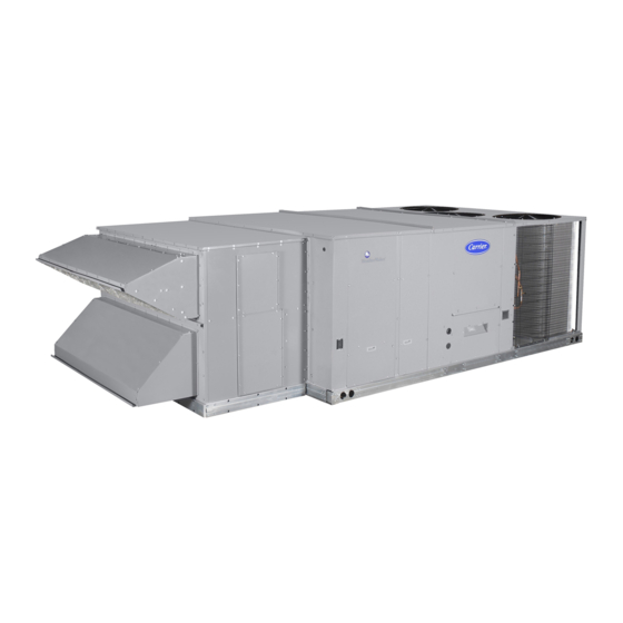
Vertical and Horizontal Low Leak EconoMi$er
Part No. CRECOMZR052A00 and CRECOMZR053A00
CONTENTS
SAFETY CONSIDERATIONS . . . . . . . . . . . . . . . . . . . 1
PACKAGE USAGE AND CONTENTS . . . . . . . . . . . . . 2
GENERAL . . . . . . . . . . . . . . . . . . . . . . . . . . . . . . . . . . . 3
ACCESSORIES LIST . . . . . . . . . . . . . . . . . . . . . . . . . . 4
VERTICAL INSTALLATION . . . . . . . . . . . . . . . . . . . . . 4
HORIZONTAL INSTALLATION . . . . . . . . . . . . . . . . . . 8
Barometric Hood Assembly . . . . . . . . . . . . . . . . . . . 12
CONFIGURATION . . . . . . . . . . . . . . . . . . . . . . . . . . . 16
EconoMi$er IV Standard Sensors . . . . . . . . . . . . . . 16
• OUTDOOR AIR TEMPERATURE (OAT) SENSOR
OPERATION . . . . . . . . . . . . . . . . . . . . . . . . . . . . . . . . 22
Sequence of Operation . . . . . . . . . . . . . . . . . . . . . . . 22
TROUBLESHOOTING . . . . . . . . . . . . . . . . . . . . . . . . 22
EconoMi$er IV System Preparation . . . . . . . . . . . . . 22
Differential Enthalpy . . . . . . . . . . . . . . . . . . . . . . . . . 22
Single Enthalpy . . . . . . . . . . . . . . . . . . . . . . . . . . . . . 22
Exhaust . . . . . . . . . . . . . . . . . . . . . . . . . . . . . . . . . 22
DCV Minimum and Maximum Position . . . . . . . . . . 23
Supply-Air Input . . . . . . . . . . . . . . . . . . . . . . . . . . . . 23
EconoMi$er IV Troubleshooting Completion . . . . . 23
IMPORTANT: Read these instructions completely before
attempting to install the EconoMi$er
Manufacturer reserves the right to discontinue, or change at any time, specifications or designs without notice and without incurring obligations.
Catalog No. 04-53480314-01
Installation Instructions
Page
IV accessory.
®
Printed in U.S.A.
Form IIK-CRECOMZR52-02
for Medium Rooftop Units
SAFETY CONSIDERATIONS
Installation and servicing of air-conditioning equipment can be
hazardous due to system pressure and electrical components. Only
trained and qualified service personnel should install, repair, or
service air-conditioning equipment.
Untrained personnel can perform basic maintenance functions of
cleaning coils and filters and replacing filters. All other operations
should be performed by trained service personnel. When working
on air-conditioning equipment, observe precautions in the
literature, tags and labels attached to the unit, and other safety
precautions that may apply.
Follow all safety codes, including ANSI (American National
Standards Institute) Z223.1. Wear safety glasses and work gloves.
Use quenching cloth for unbrazing operations. Have fire
extinguisher available for all brazing operations.
It is important to recognize safety information. This is the safety-
alert symbol
. When you see this symbol on the unit and in
instructions or manuals, be alert to the potential for personal
injury.
Understand the signal words DANGER, WARNING, CAUTION,
and NOTE. These words are used with the safety-alert symbol.
DANGER identifies the most serious hazards which will result in
severe personal injury or death. WARNING signifies hazards
which could result in personal injury or death. CAUTION is used
to identify unsafe practices, which may result in minor personal
injury or product and property damage. NOTE is used to highlight
suggestions which will result in enhanced installation, reliability,
or operation.
WARNING
ELECTRICAL SHOCK HAZARD
Failure to follow this warning could result in personal injury
and/or death.
Before beginning any modification, be certain that the main-
line electrical disconnect switch is in the OFF position. Close
the main gas supply shutoff valve. Tag disconnect switch and
gas valve with suitable warning labels.
WARNING
ELECTRICAL OPERATION HAZARD
Failure to follow this warning could result in personal injury or
death.
Disconnect power supply and install lockout tag before at-
tempting to install accessory.
Pg 1
IV Accessory
®
15 to 27.5 Tons
8-21 Replaces: IIK-CRECOMZR52-01
Advertisement
Table of Contents

Related Manuals for Carrier CRECOMZR052A00


Summary of Contents for Carrier CRECOMZR052A00
-
Page 1: Table Of Contents
Vertical and Horizontal Low Leak EconoMi$er IV Accessory ® for Medium Rooftop Units 15 to 27.5 Tons Installation Instructions Part No. CRECOMZR052A00 and CRECOMZR053A00 CONTENTS SAFETY CONSIDERATIONS Page Installation and servicing of air-conditioning equipment can be hazardous due to system pressure and electrical components. Only SAFETY CONSIDERATIONS . -
Page 2: Package Usage And Contents
PACKAGE USAGE AND CONTENTS Table 1 — Package Usage and Contents UNIT CARRIER MODEL BRYANT MODEL ICP MODEL CONTENTS Damper Assembly* Upper End Economizer Panel Bottom Panel w/Relief Damper (for vertical only) Bottom Panel #2 (for horizontal only) Side Replacement Panel (for... -
Page 3: General
The EconoMi$er IV system utilizes the latest technology available for integrating the use of free cooling with mechanical cooling for Accessories Required packaged rooftop units. The solid-state control system optimizes Carrier and Bryant ICP units units energy consumption, zone comfort, and equipment cycling by... -
Page 4: Accessories List
Power Exhaust 460 v 3 Ph CRPWREXH069A00 Power Exhaust 575 v 3 Ph CRPWREXH070A00 HH57AC078 (Carrier and Bryant only) Outdoor Air Enthalpy Sensor Fig. 2 — Upper and Bottom Panel on End of Unit AXB078ENT (ICP only) Indoor Air Enthalpy Sensor CRENTDIF004A00 Unit’s Left... - Page 5 d. Secure side panels (Items #4 and #5) to upper panel using the screws provided. e. Apply seal strip to mating flange of the hood (see Fig. 10). f. Secure hood top (Item #3) to upper panel using the Unit’s Left screws provided.
- Page 6 Insert two (2) screws through the HVAC panel and into the economizer Harness Provided Upper Panel Economizer Outside Air Damper Indoor-fan Provided Remove Bottom Panel Relief Damper Shipping With Relief Screw Fig. 9 — End View of Unit Fig. 8 — Blower Housing Apply seal strip to the back of this flange...
- Page 7 15. Install the hood assembly on to the unit (see Fig. 12 and 13). 16. Through the outdoor air hood, review and adjust the EconoMi$er IV controller settings. See “Operation” section of this manual for details. a. The standard EconoMi$er IV controller has a factory setting of 63°F for the outdoor air temperature changeover and 55°F (fixed) for the supply air temperature sensor.
-
Page 8: Horizontal Installation
POTENTIOMETER DEFAULTS SETTINGS: ECONOMIZER (FIOP / ACCESSORY) POWER EXH MIDDLE MINIMUM POS. FULLY CLOSED DCV MAX. MIDDLE DCV SET MIDDLE ENTHALPY C SETTING ECONOMIZER (ACCESSORY) MOTOR REMOTE MIN POSITION POT REMOTE POT (135 ohm) 24Vac PL6 - R FOR STD UNIT OPEN (FIOP / ACCESSORY) - Page 9 Outdoor Air Hood CRBARHOD001A00 Relief Hood Ordered Separately Field Supplied Relief Damper Return Duct Fig. 16 — Hinges and Damper on Return Duct Indoor Fan Panel Upper End Panel Shipped On Base Unit Economizer Bottom Panel Shipped On Base Unit Fig.
- Page 10 14. Assemble the outside air hood per Fig. 26-28 (see Fig. 26 for Economizer Outside hood component locations): Air Damper a. Install filters supports (Item #1) to the upper end panel using the screws provided. Insert b. Install each deflector (Item #8) on to each filter support Screw (Item #1) using the screws provided.
- Page 11 HVAC Harness Indoor-fan Bottom panel with Return duct opening Fig. 25 — Install Bottom Panel with Horizontal Return Fig. 24 — Blower Housing Duct Opening Apply seal strip to the back of this flange Apply seal strip to the back Apply seal strip of this flange to the back...
-
Page 12: Barometric Hood Assembly
Economizer outside Provided Air damper Upper panel 61 9/16" 18 3/8" Slide Into Economizer actuator Insert Position Provided bottom panel Access through left Air Screen With return duct opening Side panel Fig. 29 — End View Barometric Hood Assembly The barometric hood can be assembled in vertical or horizontal configuration. - Page 13 Fig. 31 — Shipping Location, Vertical Units Fig. 32 — Barometric Hood Box Parts Location Fig. 33 — Barometric Hood Exploded View...
-
Page 14: Barometric Hood (Horizontal Configuration)
Fig. 34 — Installed Barometric Hood Side View and Isometric View BAROMETRIC HOOD (HORIZONTAL CONFIGURATION) On the field installed economizer (CRECOMZR0**A00), a birdscreen or hardware cloth is shipped attached to the For horizontal return and field-installed economizer, install the bottom panel used for vertical applications. economizer as follows: NOTE: This panel is not used for horizontal return applications. - Page 15 Outdoor Air Hood CRBARHOD001A00 Relief Hood Ordered Separately Min 19-1/2” *Blade Bracket Field Supplied Return Duct *Provided with Economizer Relief Damper Fig. 36 — Installing CRBARHOD001A00 Over Relief Damper Fig. 37 — CRBARHOD001A00 Hood Sides and Top Caulk the backside of the mating flanges to ensure a watertight seal.
-
Page 16: Configuration
CONFIGURATION Table 4 — Supply Air Sensor Temperature/ EconoMi$er IV Standard Sensors Resistance Values OUTDOOR AIR TEMPERATURE (OAT) SENSOR TEMPERATURE (°F) RESISTANCE (ohms) The outdoor air temperature sensor is a 10 to 20 mA device used –58 200,250 to measure the outdoor-air temperature. The outdoor-air –40 100,680 temperature is used to determine when the EconoMi$er IV system... -
Page 17: Economi$Er Iv Control Modes
1 2 3 For enthalpy control, accessory enthalpy sensor (part number 55°F CRENTDIF004A00 for Carrier and Bryant, AXB078ENT for ICP) is required. Replace the standard outdoor dry bulb 1 2 3 temperature sensor with the accessory enthalpy sensor in the same 58°F... - Page 18 (29) (32) (35) (38) (41) (43) CONTROL CONTROL POINT CURVE APPROX. °F (°C) AT 50% RH (27) 73 (23) 70 (21) 67 (19) 63 (17) (24) (21) (18) (16) (13) (10) HIGH LIMIT CURVE (10) (13) (16) (18) (21) (24) (27) (29) (32)
-
Page 19: Indoor Air Quality (Iaq) Sensor Input
INDOOR AIR QUALITY (IAQ) SENSOR INPUT MINIMUM POSITION CONTROL The IAQ input can be used for demand control ventilation control There is a minimum damper position potentiometer on the based on the level of CO measured in the space or return air duct. EconoMi$er IV controller. -
Page 20: Occupancy Control
Exhaust Fan Setpoint LED lights when exhaust contact is made Minumum Damper Postion Setting Maximum Damper Demand Control Ventilation Setpoint LED lights when demand control ventilation input is above setpoint Demand Control Ventilation Setpoint LED lights when outdoor air is suitable for free cooling Free Cooling /Enthalpy... -
Page 21: Dehumidification Of Fresh Air With Dcv Control
Use the Up/Down button to select the preset number. (See Press Mode to move through the variables. Table 5.) Press Enter to lock in the selection, then press Mode to Press Enter to lock in the selection. continue to the next variable. Press Mode to exit and resume normal operation. -
Page 22: Operation
7. If connected, remove sensor from terminals SO and +. OPERATION Connect 1.2 kilo-ohm checkout resistor across terminals Sequence of Operation SO and +. When free cooling is not available, the compressors will be Put 620-ohm resistor across terminals SR and +. controlled by the zone thermostat. -
Page 23: Dcv Minimum And Maximum Position
Remove the 5.6 kilo-ohm resistor and jumper T to T1. The DCV Minimum and Maximum Position actuator should drive fully open. To check the DCV minimum and maximum position: Remove the jumper across T and T1. The actuator should Make sure EconoMi$er IV preparation procedure has been drive fully closed. - Page 24 ††† Modulation is based on the greater of DCV and supply-air sensor signals, between closed and either maximum position (DCV) or fully open (supply-air signal). © 2021 Carrier Manufacturer reserves the right to discontinue, or change at any time, specifications or designs without notice and without incurring obligations.
Need help?
Do you have a question about the CRECOMZR052A00 and is the answer not in the manual?
Questions and answers