
Related Manuals for Enerdis CA2150-M


Summary of Contents for Enerdis CA2150-M
- Page 1 INDICATEURS NUMERIQUES DE TABLEAU PROCESS - TEMPERATURE - JAUGES C.A 2150-M FRANCAIS NOTICE D´INSTRUCTIONS...
- Page 2 INDEX INTRODUCTION ....................................4 INSTRUCTIONS GENERALES ................................5 2.1. Alimentation et raccordement ..............................9 2.2. Vue frontal instrument ................................10 2.3. Guide de programmation................................10 PROGRAMMATION DES ENTREES ..............................11 3.1. Programmation entrée process ..............................13 3.1.1. Raccordement transducteur (V, mA) ........................13 3.1.2. Schéma de connexion entrée mA...........................14 3.1.3.
- Page 3 BLOCAGE DE LA PROGRAMMATION PAR SOFTWARE ........................34 6.1. Diagramme du menu de sécurité.............................. 35 OPTIONS DES SORTIES................................... 38 7.1. SORTIE SETPOINTS (seuils alarmes) ............................39 7.1.1. Présentation................................39 7.1.2. Description du fonctionnement..........................40 7.1.3. Installation................................41 7.1.4. Branchement ................................ 41 7.1.5.
- Page 4 1. INTRODUCTION Les indicateurs numériques programmables de la série C.A 2150 offrent toutes les fonctions requises pour la mesure et l’exploitation des signaux dans les milieux industriels. Le convertisseur à double rampe 15 bits et l’afficheur tricolore programmable, d’affichage ± 20000 points, autorisent des mesures précises, avec une grande résolution.
-
Page 5: Instructions Generales
2. INSTRUCTIONS GENERALES Contenu de l´emballage Manuel d´instructions L´indicateur numérique. Accessoires pour montage sur tableau (joint d´étanchéité et clips de fixation). Accessoires de raccordement (Borniers débrochables et pinces d´insertion des fils). Etiquette de raccordement incorporée à la boite. 4 Ensembles d´étiquettes avec unités de mesure. Vérifier le contenu de l´emballage. - Page 6 Sur la figure suivante on montre la situation des différentes options de sortie. Jusqu´à 3 options de sortie peuvent être présentes et opérer de façon simultanée : - 4-20mA ou 0-10V (seulement une) - RS232C ou RS485 (seulement une) - 2 RELAIS, 4 RELAIS ou 4 OPTOS (seulement une). Dimensions et montage Frontal: 96 x 48 mm Fond: 60 mm découpe panneau : 92 x 45 mm...
- Page 7 Comment entrer dans le mode de programmation? Premièrement, connecter l´instrument à l´alimentation correspondante selon le modèle. Automatiquement sera réalisé un test d´affichage on y visualisera la version de software, ensuite l´instrument se situera en mode de travail. Deuxièmement, appuyer sur la touche PRG/RUN pour entrer en mode de programmation, sur l´afficheur apparaîtra l´indication "-Pro-".
- Page 8 Accéder aux données de programmation Grâce à leur structure en arbre, les routines de programmations permettent d´accéder à un changement de paramètre sans avoir besoin de parcourir la liste complète. Avancer dans la programmation L’accès à un sous-menus se fait par l’appui de la touche - PRG/RUN.
-
Page 9: Installation
à proximité, facilement accessible pour l’opérateur et marqué comme dispositif de protection. RACCORDEMENT ET PLAGE D´ALIMENTATION CA2150-M(1) 85 V – 265 V AC 50/ 60 Hz ou 100 – 300 V DC CA2150-M(2) CONNECTEURS 22 –... -
Page 10: Guide De Programmation
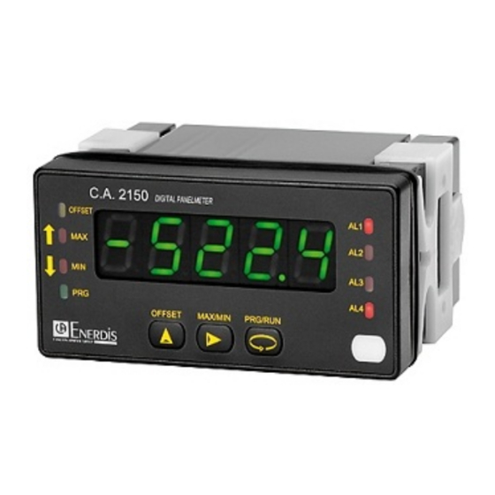
2.2 – Vue frontal instrument 2.3 - Guide de programmation A la suite, nous énumérons les différentes étapes à suivre pour programmer correctement chaque fonction. La lecture et application de certains paragraphes son obligatoires (O), recommandés (R) ou optionnels (op). Comme thermomètre Pt100: Comme indicateur de Process: Programmation de l´entrée, Pag. - Page 11 3. PROGRAMMATION DES ENTRÉES La figure suivante montre le menu de configuration d´entrée. Il Dispose de quatre sous-menus, Chacun d´eux signalés en pointillé dans le manuel, correspondants à la programmation des différents types d´entrée: process, cellule de charge, thermomètre Pt100 et thermomètre thermocouple.
- Page 12 tE M P P t10 0 -tC - -º C - -ºF - -T - -ºC - -º F - 0 .1 º 1 º 0.1º 1 º 00 .0 O ffse t 00 .0 O ffse t -P ro - -P ro - T h e r m o m è...
- Page 13 3.1 - Programmation entrée process Comme indicateur de process il est destiné à la mesure de tout type de variables de process avec indication directe en unités d´ingénierie. Le paramètre à configurer comme indicateur de process est le type d´entrée, en volts avec une plage de -10 V à +10 V ou en milliampères avec une plage de -20 mA à...
- Page 14 3.1.2 - SCHÉMAS RACCORDEMENT ENTRÉE mA (±0-20 mA/ 4-20 mA) EXCITATION PAR L’EXTERIEURE EXCITATION FOURNI PAR CA2150 Raccordement 4 fils Raccordement 4 fils EXCITATION TRANSDUCTEUR TRANSDUCTEUR EXTERIEURE +IN (mA) 0-20 mA 0-20 mA 4-20 mA 4-20 mA -IN (mA) - IN (mA) Raccordement 3 fils Raccordement 3 fils EXCITATION...
- Page 15 3.1.3 - SCHÉMAS RACCORDEM ENT ENTRÉE V (±0-10 V) Raccordement 4 fils POTENTIOMETRE +EXC (10V) EXCITATION TRANSDUCTEUR EXTERIEURE +OUT 0-10 V -OUT Raccordement 3 fils Raccordement 2 fils EXCITATION TRANSDUCTEUR EXTERIEURE 0-10 V 0-10 V Raccordement 4 fils TRANSDUCTEUR 0-10 V Raccordement 3 fils TRANSDUCTEUR Si l´excitation que doit fournir le C.A 2150-M au transmetteur doit...
- Page 16 3.2 - Programmation entrée cellule de charge Consultez la documentation du fabricant de vos cellules, surtout les spécifications de sensibilité et la tension d´excitation requise pour son alimentation. Comme indicateur pour cellule de charge sa fonction sera la mesure de charges (poids, pression, torsion...) exercées sur un dispositif raccordé à divers transducteurs type pont telles que cellules de charge, qui délivrent des niveaux de signal allant jusqu´à...
- Page 17 3.2.1 – Raccordement cellule de charge (mV/ V) Consultez les recommandations de raccordement à la Page 9. RACCORDEMENT SIGNAL D´ENTRÉE Vue postérieure de l´instrument PIN 1 = -EXC [sortie excitation (-)] PIN 2 +EXC [ne pas raccorder] PIN 3 = +EXC [sortie excitation +5V à...
- Page 18 3.3 - Programmation entrée thermomètre Pt100 Quand on configure l´instrument comme thermomètre pour sonde Pt100 à trois fils, les plages de température et résolution disponibles sont: Entrée Plage (res. 0.1 º) Plage (res. 1º) -100.0 a +800.0 ºC -100 a +800 ºC Pt100 -148.0 a +1472.0 ºF -148 a +1472 ºF...
- Page 19 3.3.1 – Raccordement de l’entrée Pt100 Vue postérieure de l’instrument RACCORDEMENT SIGNAL D’ENTREE PIN 1 = ne pas raccorder PIN 2 = ne pas raccorder PIN 3 = ne pas raccorder PIN 4 = Pt100 PIN 5 = ne pas raccorder PIN 6 = ne pas raccorder PIN 7 =...
- Page 20 3.4 - Programmation entrée thermocouple Quand on configure l´instrument comme thermomètre thermocouple, les plages de température et de résolution disponibles sont: Entrée Plage (res. 0,1 º) Plage (res. 1º) -50,0 a +850,0 ºC -50 a +850 ºC Thermo couple -58,0 a +1562,0 ºF -58 a +1562 ºF -50,0 a +1250,0 ºC -50 a +1250 ºC...
- Page 21 3.4.1 - Raccordement de l´entrée thermocouple (J, K, T) Consultez les recommandations de raccordement à la Page 9. RACCORDEMENT SIGNAL D´ENTRÉE Vue postérieure de l´instrument PIN 1 = ne pas raccorder PIN 2 = ne pas raccorder PIN 3 = ne pas raccorder PIN 4 = ne pas raccorder PIN 6 = ne pas raccorder...
- Page 22 4. PROGRAMMATION DE L´AFFICHAGE CndSP ModtA SCAL FILtP round brIGH tEACH tArE3 InP 1 tArE1 tArE2 InP 1 ±88.888 ±88.888 dSP 1 dSP 1 -Pro- -Pro- -Pro- -Pro- ±18888 ±18888 ±18.888 ±18.888 Point décimal InP 2 InP 2 ±88888 ±88888 dSP 2 dSP 2 ±18888...
- Page 23 4.1. Echelle Il est nécessaire de programmer l´échelle de l´instrument seulement lorsque celui-ci est configuré comme indicateur de process ou cellule de charge. La programmation de l´échelle consiste à assigner une valeur d ´affichage à chaque valeur du signal d´entrée. échelle directe échelle inverse Dans le cas de...
- Page 24 4.1.1 Programmation de l´Echelle Il y a deux méthodes pour programmer l´échelle, la méthode SCAL et la méthode tEACH. Dans le diagramme ci-dessous nous avons développé le menu SCAL comme exemple ; ce diagramme est exactement le même pour le menu tEACH. CndSP SCAL InP 1...
- Page 25 Méthode SCAL Les valeurs d´entrée et d´affichage se programment manuellement. Cette méthode est adéquate quand on connaît la valeur du signal délivré par le transducteur à chaque point du process. Méthode tEACH Les valeurs d´affichage se programment manuellement en fonction des mesures émises en entrée. Cette méthode est applicable une foie l’installation process terminée.
- Page 26 Filtre P - [FILtP] Filtre de moyenne pondérée. La valeur sera modifiée au moyen de la touche - MAX/MIN. Ce paramètre fixera en ordre inverse la fréquence de coupe du filtre passe-bas, le filtre étant désactivé pour la valeur 0. Il n´est pas disponible quand l´instrument est configuré pour mesurer la à...
- Page 27 TARE 1 En mode tArE1, en appuyant sur la touche - OFFSET, l´instrument enregistre la valeur montrée par l´affichage sauf lorsqu´elle est en dépassement d´échelle. La Led OFFSET s´illuminera et à partir de ce moment, la valeur montrée est la valeur nette, c´est à dire, la mesure moins la valeur enregistrée précédemment dans la tare. Si on appuie sur la même touche lorsque l´instrument a une tare, la valeur montrée à...
- Page 28 5. FONCTIONS PAR CLAVIER ET PAR ENTRÉES LOGIQUES 5.1 - Fonction par clavier Au moyen de clavier on peut contrôler diverses fonctions qui auront différentes actions selon le mode de fonctionnement de l´instrument: En mode -RUN-: Fonction TARE (Offset) et Fonction RESET TARE (Offset) Elles ont été...
- Page 29 En mode -Prog-: RECUPERATION PROGRAMMATION D´USINE – Touche OFFSET pendant 3s L´entrée d´un code d´accès permet le reset complet des paramètres de votre configuration, ce code est le 74. Une foie rentrée et validé par l´instrument montre la légende LoAdIng dEFAuLt ConFIGurAtIon, puis à continuation StorE, ce qui signifie que la configuration usine a été chargé et remplace la précédente.
- Page 30 5.2 - Fonctions par entrées logiques Le connecteur CN3 est composé de 3 entrées opto-couplées qui s´activent au moyen de contacts ou niveaux logiques provenant d´une électronique externe. On peut donc ajouter 3 fonctions supplémentaires à celles existantes du clavier. Chaque fonction est associée à...
- Page 31 5.2.1 - Diagramme des fonctions logiques - (entrées logiques) Rentrez le numéro de la fonction voulu (voir tableau page 32) sur l’entrée désirée. Les fonctions se déclencherons à distance par l’intermédiaire des impulsions ou niveaux logiques envoyés sur les entrées. LoGIn Inp-1 Inp-2...
- Page 32 5.2.2 - Table de fonctions programmables - (entrées logiques) Nº Fonction Description Activation par Désactivée Aucune Aucune TARE * Ajoute la valeur affichée à la mémoire de tare et passe l´affichage à zéro. Front descendant RESET TARE * Ajoute la mémoire de tare à l´affichage et efface la mémoire de tare. Front descendant Fait afficher la valeur pic.
- Page 33 5.2.3 – Programmation des fonctions Une fois accédé au menu de configuration des fonctions logiques, l´utilisateur peut à sélectionner au moyen de la touche une fonction énuméré dans le tableau précédent. Si l´utilisateur sélectionne une des fonctions logiques 7, 8 ou 9, l´instrument affichera l’un T-OFF T-ON de ces deux messages.
- Page 34 6. BLOCAGE DE LA PROGRAMMATION PAR SOFTWARE L´instrument est livré avec la programmation débloquée, donnant ainsi accès à tous les niveaux de programmation. Une fois la programmation de l´instrument terminée nous recommandons de prendre les mesures de sécurité suivantes: Bloquer l´accès à la programmation, afin d’éviter des modifications des paramètres programmés. Bloquer les fonctions actives du clavier pour éviter des erreurs de manipulation (expl : OFFSET du clavier).
- Page 35 Les menus ou sous-menus qui peuvent être bloqués sont: • Programmation Seuil 1 (SEt 1). • Programmation Seuil 2 (SEt 2). • Programmation Seuil 3 (SEt 3). • Programmation Seuil 4 (SEt 4). • Programmation de l´entrée (InPut). • Affichage (dISP). •...
- Page 36 ENTER CodE 8888 =Code? LISt CHANG CoLor (liste param) totLC - - - - (bloc. Total) (Vert) (Jaune) (Rouge) ≠----? (Jaune) (Vert) (Rouge) Pag 37 Note: La sélection de la couleur des alarmes s´effectue dans le menu de setpoints (Page 44) StorE StorE...
- Page 37 0 : permet sa programmation 1 : bloque l´accès à la programmation Pag. 36 * Elles apparaissent seulement si les options correspondantes sont montées Anout StorE =Code? rSout SEt 1 LoGIn SEt 2 tArE SEt 3 StVAL SEt 4 StorE InPut dISP...
- Page 38 7. OPTIONS DES SORTIES Comme option, le modèle C.A 2150-M peut disposer d´une ou plusieurs options de sorties de contrôle ou communication, augmentant ainsi ses prestations de façon notable: Toutes les options mentionnées sont opto couplées par rapport au signal d´entrée et d’ alimentation. Facilement adaptables au circuit de base au moyen de connecteurs enfichables, elles sont, une fois installées, reconnues par l´instrument qui ouvre leur module de programmation au moment de la mise sous tension de l´appareil.
- Page 39 7.1 – SORTIE SETPOINTS ( seuils alarmes ) 7.1.1 – Présentation Une option de 2 ou 4 SEUILS programmables sur toute la plage d´affichage, peut s´ajouter à l´instrument pour lui donner la capacité d´alarme avec un contrôle visuel par LEDs individuelles et sorties par relais ou transistor. Tous les seuils disposent d´action retardée programmable par temporisation (en secondes) ou hystérésis asymétrique (en points d´affichage) et le choix du mode d´activation HI/LO est sélectionnable.
-
Page 40: Description Du Fonctionnement
7.1.2 – Description du fonctionnement Les alarmes son indépendantes, elles s´activent quand la valeur d´affichage atteint la valeur de seuil programmé par l´utilisateur. La programmation de ces alarmes exige de prédéterminer les paramètres suivants: a. MODE COMPARAISON NET/ GROSS En mode “NET” la valeur de consigne est comparée avec la valeur nette d´affichage. En “GROSS”, la comparaison se fera avec la somme de net + tare (offset). -
Page 41: Installation
7.1.3 – Installation Extraire le boîtier et rompre les parties plastiques prédécoupé. L´orifice effectué permettra de sortir le connecteur sur la partie postérieure de l´instrument de l´option choisie : 2RE, 4RE ou 4NPN. Placer la carte option sur le connecteur M1 et plugger en même temps le tenon de la carte option dans l’ouverture de la carte mère prévue à... -
Page 42: Spécifications Techniques
Chaque option de sortie est livrée avec une étiquette adhésive sur laquelle est indiqué le raccordement de chacune des options. Pour une meilleure identification de l´instrument, cette étiquette doit être située sur la partie supérieure du boîtier, de façon opposée à l´étiquette d ’identification de l´instrument. - Page 43 7.1. 6 - Diagramme du menu de Setpoints (seuils alarmes) la programmation complète n´est montré que pour un seul des seuils, même manip pour les autres . SEtP SEt 4 SEt 2 SEt 1 SEt 3 -off- -on- On peut seulement les programmer si une option a été...
- Page 44 7.1.7 – Accès directe à la programmation de la valeur des setpoints Si une des options correspondantes aux seuils a été installée, il est possible d´accéder à la valeur des seuils directement sans avoir à passer par le menu de programmation en appuyant sur la touche - OFFSET.
- Page 45 7.2 – SORTIE RS232C / RS485 7.2.1 – Présentation L´ option de sortie RS232C consiste en une option additionnelle qui s´installe sur le connecteur enfichable M2 de la carte mère de l´instrument. L´option dispose d´un connecteur téléphonique de 4 voies avec sortie sur la partie postérieure de l´instrument.
- Page 46 7.2.2 – Branchement La liaison RS 232C permet de raccorder un indicateur C.A RS232 2150 à un dispositif maître, à une unité centrale par exemple. 4 = GND 3 = RxD 2 = TxD (Connecteur type RJ9) 1 = RTS La liaison RS 485 permet de raccorder en réseau jusqu’à...
- Page 47 7.2.3 – Raccordement en réseau par liaison RS485 On peut raccorder en réseau jusqu’à 31 indicateurs C.A 2150 ou C.A 2200 (tous modèles confondus) sur un appareil maître. Chaque indicateur devra avoir une adresse unique, comprise entre 00 et 99. L’adresse 00 est commune à tous les appareils du réseau : elle sera utilisée par exemple pour envoyer un ordre simultané...
- Page 48 Pont pour résistance de ligne sur carte option RS485 Le raccordement en réseau par interface RS485 nécessite de refermer la ligne de communication en ses extrémités au moyen d’une résistance (Rt) de 120 Ω. La carte LIAISON RS485 des indicateurs C.A 2150 intègre une résistance pré-cablée, qui sera “...
- Page 49 7.2.4 - Diagramme du menu Sortie RS rSout bAud trAnS 1200 4800 9600 19200 Prt 1 Prt 2 Prt 3 RS4? -Pro- Prt1= CA Prt2=ISO 1745 Prt3=MODBUS -Pro- -Pro- 1: dLY = 30 ms 2: dLY = 60 ms 3: dLY = 100 ms...
- Page 50 PROTOCOLE CA Le format de chaque caractère est de 1 bit de START, 8 bits de DONNEES, pas de PARITÉ et 1 bit de STOP. • FORMAT DU MESSAGE A ENVOYER A L´INSTRUMENT Un message dirigé à l´instrument doit consister en la série suivante de caractères ASCII: X ......
- Page 51 PROTOCOLE ISO 1745 Le format de chaque caractère est de 1 bit de START, 7 bits de DONNÉES, 1 bit de PARITÉ PAIRE et 1 bit de STOP. • FORMAT DU MESSAGE A ENVOYER A L´INSTRUMENT Un message partant du dispositif maître doit consister en la série suivante de caractères: X ..
- Page 52 • FORMAT DU MESSAGE DE REPONSE DE L´INSTRUMENT Le format typique des messages envoyés depuis l´instrument en réponse à une commande du dispositif maître est le suivant: 1. Dans le cas de commandes réclamant le retour d´une valeur (de type demande de données) : X ....
- Page 53 Table des fonctions Protocole Fonction Type de fonction Transmission de la valeur Min mémorisée Transmission de données Transmission de la valeur Max mémorisée Transmission de la valeur d’offset Transmission de la valeur de l ‘affichage Transmission de la valeur du seuil 1 Transmission de la valeur du seuil 2 Transmission de la valeur du seuil 3 Transmission de la valeur du seuil 4...
- Page 54 7.2.5 – Logiciel de programmation L’ensemble des programmes proposés permettent d’une manière simple de configurer, programmer et vérifier la totalité d’un équipement de la gamme CA2150 et CA2200, dotés d’une carte de communication RS232C ou RS485, raccordé à un PC. A l’installation de chaque programme, il est conseillé...
-
Page 55: Sortie Analogique
7.3 – SORTIE ANALOGIQUE 7.3.1 – Présentation Deux plages de sortie analogique (0-10 V et 4-20 mA) peuvent être incorporées à la gamme des C.A2150 au moyen d´une option additionnelle ; soit la carte 0-10V pour sortir en tension soit la carte 4-20mA pour sortir en courant. Elles s´installent sur la carte mère au moyen du connecteur M3 et ne peuvent être utilisées simultanément. - Page 56 7.3.3 – Branchement Chaque option de sortie est livrée avec une étiquette adhésive sur laquelle est indiqué le raccordement de chacune des options (voir Fig.). Pour une meilleure identification de l´instrument, cette étiquette doit être située sur la partie supérieure du boîtier, de façon opposée à...
- Page 57 7.3.4 – Spécifications techniques CARACTÉRISTIQUES SORTIE 4-20mA SORTIE 0-10V RESOLUTION 13 BITS 13 BITS PRECISION 0.1% F.E. ±1BIT 0.1% F.E. ±1BIT TEMPS DE REPONSE 50 ms 50 ms DÉRIVE THERMIQUE 0.5 µA/ºC 0.2 mV/ºC CHARGE MAXIMUM <= 500 >=10 K 7.3.5 - Diagramme du menu Sortie Analogique Anout outHI...
-
Page 58: Garantie
GARANTIE Notre garantie s’exerce, sauf stipulation expresse, pendant trois ans après la date de mise à disposition du matériel (extrait de nos Conditions Générales de Vente, communiquées sur demande). En cas de constatation d´un quelconque défaut où avarie dans l´utilisation normale de l´instrument pendant la période de garantie, il est recommandé... -
Page 59: Specifications Techniques
SPECIFICATIONS TECHNIQUES SIGNAL D´ENTRÉE Entrée Température • Compensation jointe froide ..........-10 ºC a +60 ºC • Jointe froide ............±(0.05 ºC/ ºC +0.1 ºC) • Configuration..........différentiel asymétrique • Courant excitation Pt100 ............< 1 mA DC • Résistance max. fils ..........40 Ω/ câble (équilibré) Entrée Process Tension Courant... - Page 60 AFFICHAGE FILTRES • Principal ...-19999/ 19999, 5 digits tricolore 14 mm Filtre P • • Fréquence de coupe ......de 4Hz a 0.05Hz Point décimal........programmable • • LEDs....... 4 de fonctions et 4 de sorties Pente ............20 dB/décade • rafraîchissement affichage •...
- Page 61 30-05-2008 code MS01-7367 Ed.3 1-9 Rue d’Arcueil 92120 MONTROUGE - France Tél : (33) 01 47 46 78 00 - Fax : (33) 01 42 53 64 78 - www.enerdis.com...
- Page 62 MULTIFUNCTION INDICATOR FOR PROCESS - TEMPERATURE - LOAD CELL C.A 2150-M INSTRUCTION MANUAL ENGLISH...
- Page 63 INDEX INTRODUCTION ..............................4 GETTING STARTED..............................5 2.1. Power supply and connectors .......................... 9 2.2. Instrument front panel ..........................10 2.3. Programming instructions..........................10 INPUT PROGRAMMING ............................11 3.1. Process input Programming ........................... 13 3.1.1. Transducer connection (V, mA)....................13 3.1.2.
- Page 64 PROGRAMMING LOCK-OUT BY SOFTWARE ......................34 6.1. Security menu diagram ..........................35 OUTPUT OPTIONS..............................38 7.1. SETPOINTS OUTPUT............................. 39 7.1.1. Introduction ..........................39 7.1.2. Functioning description ....................... 40 7.1.3. Set up............................41 7.1.4. Wiring ............................41 7.1.5. Technical Specifications....................... 42 7.1.6.
- Page 65 1. INTRODUCTION The CA2150-M model is a digital multifunction instrument which allows the user to program the input as a: - PROCESS INPUT (V, mA) - LOAD CELL INPUT (mV) - Pt100 INPUT - THERMOCOUPLE INPUT (J, K, T) The basic instrument is a soldered assembly composed of a main board, a tricolor programmable display and a power circuit.
-
Page 66: Getting Started
Digital panel meter. Accessories for panel mounting (sealing gasket and fixing clips). Accessories for wiring connections (plug-in terminal block connectors with a fingertip key). Wiring label stuck to the CA2150-M case. 4 set of labels with engineering units. Check the packing contents. - Page 67 The figure below shows the locations of the different output options available. 3 output options can be present and operate in a manner simultaneous : - 4-20mA or 0-10V (only one) - RS232C or RS485 (only one) - 2 RELAYS, 4 RELAYS o 4 OPTO (only one). Dimensions and mounting Front: 96 x 48 mm Depth: 60 mm Panel cut-out: 92 x 45 mm...
-
Page 68: Input Selection
How to get into programming mode? First, plug the instrument to the corresponding supply, automatically a display test will be done and after that the software version will be shown then the instrument will go to work mode. Second, press the key to enter into the programming mode, the indication "-Pro-"... - Page 69 Accessing to programmed parameters Thanks to the tree structure, the programming routines allow to access to change one parameter without passing through the whole list of parameters. To advance through programming The progress through the programming routines is done by pressing key.
-
Page 70: Installation
2.1 – Power Supply and connectors WARNING: If not installed and used in accordance with these instructions, protection against hazards may be impaired. In order to guarantee the electromagnetic compatibility, the following guidelines should be kept in mind: Power supply wires may be routed separated from signal wires. Never run power and signal wires in the same conduit. -
Page 71: Programming Guide
2.2 –Instrument frontal view 2.3 – Programming guide The different steps to be followed for a correct programming of each type of function are detailed below. The reading and application of some paragraphs are obligatory (O), recommendable (R) or optional (op). As Process indicator: As thermometer Pt100: Input Configuration, Page. -
Page 72: Input Configuration
3. INPUT CONFIGURATION The figure below shows the input configuration menu. Divided into four submenus, each one of them separated by the dotted line in the manual, each menu corresponds to the programming of the different types of input: process, load cell, thermometer Pt100 and thermometer thermocouple. - Page 73 tE M P P t10 0 -tC - -º C - -ºF - -T - -ºC - -º F - 0 .1 º 1 º 0.1º 1 º 00 .0 O ffse t 00 .0 O ffse t -P ro - -P ro - Pt100 thermometer: Thermocouple Thermometer:...
- Page 74 3.1 – Program process input As process indicator it is designed to measure all kinds of process variable with direct indications in engineering units. The parameter to configure as process indicator is the input type, in volts in a -10 V to 10 V range and in milliamps in a -20 mA to 20 mA range.
- Page 75 2 wire Connection (only 4-20mA) (only 4-20mA) EXTERNAL TRANSDUCER TRANSDUCER EXCITATION 4-20 mA 4-20 mA If the excitation supplied by CA2150-M to the transducer has to be 10 or 5 V connect the + EXC wire to PIN3 instead of PIN2...
- Page 76 0-10 V 4 wire Connection TRANSDUCER 0-10 V 3 wire Connection TRANSDUCER If the excitation supplied by CA2150-M to the transducer has to be 10 or 5 V connect the + EXC wire to PIN3 instead of PIN2 0-10 V...
- Page 77 3.2 – Programming of Load cell input Refer to cell manufacturer’s documentation, particularly with respect to the cell sensitivity and supply voltage specifications. As load cell indicator the meter’s function is to measure forces (weight, pressure, torque...) applied to a device connected to several bridge type transducers such as load cell, which supply signal levels up to ±150 mV.
- Page 78 3.2.1 – Load cell connection (mV/ V) Refer to wiring guidelines in Page. 9. CONNECTOR SIGNAL INPUT Instrument’s rear view PIN 1 = -EXC [excitation output (-)] PIN 2 = +EXC [no connection] PIN 3 = +EXC [excitation output +5V or 10 V (+)] PIN 4 = [no connection] PIN 5 =...
- Page 79 3.3 - Programming of Pt100 thermometer input When configuring the meter as thermometer for 3 wires Pt100 sensors, the temperature ranges and resolution available are: Input Range (res. 0.1 º) Range (res. 1º) -100.0 to +800.0 ºC -100 to +800 ºC Pt100 -148.0 to +1472.0 ºF -148 to +1472 ºF...
- Page 80 3.3.1 - Pt100 input connection Instrument’s rear view CONNECTOR SIGNAL INPUT PIN 1 = No connection PIN 2 = No connection PIN 3 = No connection PIN 4 = Pt100 PIN 5 = No connection PIN 6 = No connection PIN 7 = Pt100 PIN 8 =...
- Page 81 3.4 – Programming of Thermocouple input When configuring the meter for thermocouple input, the temperature ranges and resolution available are: Input Range (res. 0,1 º) Range (res. 1º) Thermo- -50,0 a +850,0 ºC -50 a +850 ºC couple J -58,0 a +1562,0 ºF -58 a +1562 ºF Thermo- -50,0 a +1250,0 ºC...
- Page 82 3.4.1 – Thermocouple (J, K, T) input connection Refer to wiring guidelines in Page. 9. CONNECTOR SIGNAL INPUT Instrument’s rear view PIN 1 = No connection PIN 2 = No connection PIN 3 = No connection PIN 4 = No connection PIN 6 = No connection PIN 7 =...
-
Page 83: Display Configuration
4. DISPLAY CONFIGURATION CndSP ModtA SCAL tEACH FILtP round brIGHt tArE3 InP 1 tArE1 tArE2 InP 1 ±88.888 ±88.888 dSP 1 dSP 1 -Pro- -Pro- -Pro- -Pro- ±18888 ±18888 ±18.888 ±18.888 Decimal point InP 2 InP 2 ±88888 ±88888 dSP 2 dSP 2 ±18888 ±18888... - Page 84 4.1. Scaling It is only necessary to scale the meter when it has been configured for process a load cell. Scaling consist of assigning a display value to each input signal value. Direct scale Reversed scale In linear processes it is achieved by programming two coordinates (input1, display1) and (input2, display2), display2 display2...
- Page 85 4.1.1 Programming of the scale There are two methods for programming the scale, the SCAL method and the tEACH method. In the following diagram the SCAL menu has been developed an a example, it is exactly the same menu than the tEACH menu. CndSP SCAL InP 1...
- Page 86 SCAL method The input and display values are programmed manually. This method can be used when the value of the signal supplied by the transducer at each points of the process is known. tEACH method The input values are introduced directly from the signal present in the input connector when each point is programmed. The display values are programmed manually.
- Page 87 Filter P - [FILtP] Filter of ponderated average. The value will be modified through the key. This parameter will set in reverse order the cut-off frequency of the low pass filter, getting the filter deactivated for 0 value. Not available when the instrument is configured for temperature measurement. Will take each one of the values by pressing successively on the key.
- Page 88 100 Kg, and the net weight 75 Kg. I n the weighing process is used a load cell connected to a CA2150-M instrument and we need to know the liquid net weigh in each instant of the process. By selecting this tare mode, the net value would be introduced via edition following the enclosed diagram.
-
Page 89: Keyboard Functions
5. KEYBOARD AND CONNECTOR FUNCTIONS 5.1 – Keyboard functions Several functions can be controlled via keyboard that will produce different actions depending on the instrument operating mode: Mode -RUN-: OFFSET (TARE) and RESET OFFSET functions Explained in the previous paragraph. MAX/MIN function Activated after pressing on the key. - Page 90 In -Prog- mode: 3s (RETURN TO FACTORY PROGRAMMING) Allows entering a code of access to the reset of the configuration parameters, this code is 74. When entering this code the instrument shows the LoAdIng dEFAuLt ConFIGurAtIon legend, following StorE, which means that they have been stored in the non volatile memory of the instrument. Factory configuration Pro- INPUT: Process 0 - 10V...
-
Page 91: Connector Functions
5.2 – Connector functions The connector CN3 provides 3 opto-coupled inputs that can be operated from contacts logic levels supplied by an external electronic system. Three different functions may be then added to the functions available from the front panel keys. Each function is associated to a pin (PIN 2, PIN 3 y PIN 4) that is activated applying a low level, in each one, with respect to PIN 1 or COMMON. - Page 92 5.2.1 – Logic functions diagram Return the desired number of the function (see table page 32) on the desired input. The functions will be activated remotely by the intermediary of the impulses or logical levels envoys on the inputs. LoGIn Inp-1 Inp-2 Inp-3...
- Page 93 5.2.2 - Table of programmable functions - (Logical inputs) Nº Function Description Activation by Deactivated None None TARE * Adds the current display value to the tare memory and sets the display to zero. Falling edge RESET TARE * Adds the tare memory to the display value and clears the tare memory. Falling edge PEAK Displays the peak value.
-
Page 94: Programming The Functions
0x18, 0x23, ”01”, 0x0D, “NET: +1234.5”, 0x0D, 0x18, 0x4A, 0x06, 0x18, 0x48 The CA2150-M has to be programmed to work under protocol ASCII (Prt1) y (dLY 1). See Page 47 If the selected function is number 12 and any of the 2RELAYS, 4RELAYS, 4NPN, options is... - Page 95 6. PROGRAMMING LOCK OUT BY SOFTWARE The instrument is delivered with the programming locked out, giving access to all the programming levels. Once completed the instrument programming we recommend the following security measures be taken: Lock out the programming access to prevent from programmed parameters modifications. Lock out keyboard functions to prevent from accidental modifications.
-
Page 96: Security Menu Diagram
Menus or submenus that can be locked out are: • Setpoint 1 configuration (SEt 1). • Setpoint 2 configuration (SEt 2). • Setpoint 3 configuration (SEt 3). • Setpoint 4 configuration (SEt 4). • Input configuration (InPut). • Scaling (SCAL). •... - Page 97 ENTER CodE 8888 =Code? LISt CHANG CoLor (list param) totLC - - - - (bloc. Total) (Green) (Yellow) (Red) ≠----? (Yellow) (Red) (Green) Pag 37 Note: the color selection of the alarms is made in the setpoints menu (Page 44) StorE StorE...
- Page 98 0 allows its programming 1 locks the access to programming Pag. 36 * Only appear if the corresponding options have been installed Anout StorE =Code? rSout SEt 1 LoGIn SEt 2 tArE SEt 3 StVAL SEt 4 StorE InPut dISP...
-
Page 99: Output Options
7. OUTPUT OPTIONS Optionally, model CA2150-M can incorporate one or several output options for control or communication: All mentioned options are opto-isolated with respect to input signal and power supply. The output cards are easily installed on the meter’s main board by means of plug-in connectors and each one activates its own programming modules that provides complete software configuration. -
Page 100: Setpoints Output
7.1 – SETPOINTS OUTPUT 7.1.1 – Introduction An option of 2 or 4 SETPOINTS, programmable within the full display range, can be incorporated to the unit thus providing alarm and control capabilities by means of individual LED indicators and relay or transistor outputs. All the setpoints provide independently programmable value, time delay (in seconds), asymmetrical or symmetrical hysteresis (in counts of display) and selectable HI/LO acting. -
Page 101: Description Of Operation
7.1.2 –Description of operation As programmed like independent setpoints, the alarm outputs activate when the display value reaches the user-programmed value. The independent alarms programming requires definition of the following basic parameters: a. COMPARISON NET/ GROSS In “NET” mode will compare the setpoint value with the display net value. In “GROSS” mode, the comparison will be with the sum net + tare. - Page 102 7.1.3 – Installation Lift out the electronics assembly from the case and use a screw-driver to push on the junctions between the case and the shadow areas to detach them from the case. See fig. The so performed orifice will allow any of the setpoints (2RE, 4RE, 4NPN) board output connectors be brought out at the rear of the instrument.
- Page 103 Each output card is supplied with an adhesive label that indicates the wiring connections of each option. To help identifying each terminal, this label should be placed in the lower side of the meter case, beside the basic functions label. NOTE: In case that the outputs are used to drive inductive loads, it is recommended to add an RC network between the coil terminals (preferably) or between the relay contacts to limit electromagnetic effects.
- Page 104 7.1. 6 Setpoints menu diagram The complete programming of one of the setpoints is showed here, it is valid for the rest of the setpoints. SEtP SEt 4 SEt 1 SEt 2 SEt 3 -off- -on- They can only be programmed if an 4RE, 4NPN option has been installed or ±188.88 if the logic function nº...
- Page 105 7.1.7 – Direct access to the setpoints value programming If any of the options corresponding to the setpoints has been installed, it is possible to accede directly to the setpoints value without need to go through the programming menu just by pressing the key in PROG mode, as showed in diagram below, supposing that the card installed are 4RE, 4NPN, if it is the 2RE card only Set1 y Set2 would appear.
- Page 106 7.2 –RS232 / RS485 OUTPUT 7.2.1 – Introduction The RS232C output option consists of an additional card that is installed in the M2 plug-in connector of the instrument’s main board. The option incorporates one 4 wires telephone socket with output at the the rear of the instrument. The RS485 output option consists of an additional card that is also installed in the M2 plug-in connector of the instrument’s main board.
- Page 107 7.2.2 – Wiring The liaison RS 232C allows linking an indicator CA 2150 RS232 to a device master, to a computer for example. 4 = GND (Connector type RJ9) 3 = RxD 2 = TxD 1 = RTS RS485 The liaison RS 485 permit to link in network until 31 indicators CA 2150 or CA 2200 to a device master.
- Page 108 7.2.3 –Connection in a network by RS485 link One can link in network until 31 indicators C.A 2150 or C.A 2200 (all confused models) on a device master. Every informer will have to have a unique address, understood between 00 and 99. The address 00 common east to all the devices of the network: she will be used for example to send a simultaneous order of discount to zero of the memories MIN, MAX or OFFSET.
- Page 109 Bridge for line resistor on RS485 card option The connection in network by interface RS485 necessitates to close the communication line in its extremities by means of a resistor (Rt) of 120 Ω. The card RS485 of the indicators C.A 2150 upright one a resistor incorporated, that will be “...
- Page 110 7.2.4 - RS output menu diagram rSout bAud trAnS 1200 4800 9600 19200 Prt 1 Prt 2 Prt 3 RS4? -Pro- Prt1= CA Prt2=ISO 1745 Prt3=MODBUS -Pro- -Pro- 1: dLY = 30 ms 2: dLY = 60 ms 3: dLY = 100 ms...
-
Page 111: Ascii Protocol
ASCII PROTOCOL The Transmission format is: 1 START bit, 8 DATA bits, NO parity bit and 1 STOP bit. • MESSAGE FORMAT TO BE SENT A message sent to the instrument must be composed of the following sequence of ASCII characters: X ...... - Page 112 ISO 1745 PROTOCOL The transmission format is: 1 START bit, 7 DATA bits, 1 EVEN PARITY bit and 1 STOP bit. • MESSAGE FORMAT TO BE SENT The message format, as sent from the master device, must consist of the following sequence of characters: X ..
- Page 113 • MESSAGE FORMAT FROM INSTRUMENT The format of a message as sent from the instrument in response to a command from the master device is the following: 1. In case of commands that ask for transmission of a value (data request type): X ....
-
Page 114: List Of Commands
List of commands Protocol Fonction Type of fonction Valley value Request of data Peak value Tare or offset value Display value Setpoint 1 value Setpoint 2 value Setpoint 3 value Setpoint 4 value Peak reset Command Valley reset Tare reset Tare the display Change the setpoint1 value in memory Parameter... - Page 115 7.2.5 – Programmation software The body of the proposed programs allow in a simple way to configure, program and verify the entirety of an equipment of the range CA2150 and CA2200, endowed with a communication card RS232C or RS485, linked to a computer. To the every program installation, it is counseled to follow the dialog pictures presented to the screen.
-
Page 116: Analog Output
7.3.1 – Introduction Two ranges of analog output (0-10 V and 4-20 mA) can be incorporated to the CA2150-M by means of an additional card, either the 0-10V card for voltage output or the 4-20mA card for current output, which is installed on the meter's main board via plug-in connector M3, both cards, cannot be used simultaneously. - Page 117 7.3.3 – Wiring Each output card is supplied with an adhesive label that indicates the wiring connections of each option (see fig.). To help identifying each terminal, this label should be placed in the lower side of the meter case, beside the basic functions label. (4-20 mA) (0-10 V) Section to...
- Page 118 7.3.4 – Technical specifications CHARACTERISTICS OUTPUT 4-20mA OUTPUT 0-10V RESOLUTION 13 BITS 13 BITS ACCURACY 0.1% F.E. ±1BIT 0.1% F.E. ±1BIT RESPONSE TIME 50 ms 50 ms THERMAL DRIFT 0.5 µA/ºC 0.2 mV/ºC MAXIMUM LOAD <= 500 >=10 K 7.3.5 - Analog output menu diagram Anout outHI Display value Hight for 20 mA / 10 V output...
-
Page 119: Warranty
WARRANTY The instruments are warranted against defective materials and workmanship for a period of three years from date of delivery. If a product appears to have a defect or fails during the normal use within the warranty period, please contact the distributor from which you purchased the product. This warranty does not apply to defects resulting from action of the buyer such as mishandling or improper interfacing. -
Page 120: Technical Specifications
TECHNICAL SPECIFICATIONS INPUT SIGNAL Temperature input • Cold junction compensation .............. -10 ºC a +60 ºC • • Configuration ..............asymmetric differential Cold junction ................ ±(0.05 ºC/ ºC +0.1 ºC) • Pt100 sensor excitation ................< 1 mA DC • Max. Lead resistance .............. 40 Ω/ cable (balanced) Process input Voltage Current... - Page 121 DISPLAY FILTERS • Principal ..-19999/ +19999, 5 digits tricolor 14 mm Filter P • • Decimal point ........programmable Cut-off frequency ......... 4Hz to 0.05Hz • • LEDs......4 for functions and 4 for outputs Slope ............20 dB/decade • Display update rate •...
- Page 122 30-05-2008 code MS01-7367-Ed.3 1-9 Rue d’Arcueil 92120 MONTROUGE - France Tél : (33) 01 47 46 78 00 - Fax : (33) 01 42 53 64 78 - www.enerdis.com...
Need help?
Do you have a question about the CA2150-M and is the answer not in the manual?
Questions and answers