Advertisement
Quick Links
IMPORTANT: Before you install the automatic gate lock be sure your gate is level, moves freely
on its hinges, and does not bind or drag against the ground.
Installation Manual
PLEASE NOTE: Because of the various mounting applications, no mounting hardware is provided with the
Automatic Gate Lock. All necessary mounting hardware can be obtained from your local hardware store; all
other hardware is provided.
This manual shows two examples of the most common installations, and should provide insight into most other
applications. If you have any questions during installation, please call (800) 543-1236 for technical support.
FM143/FM144 Installation Manual
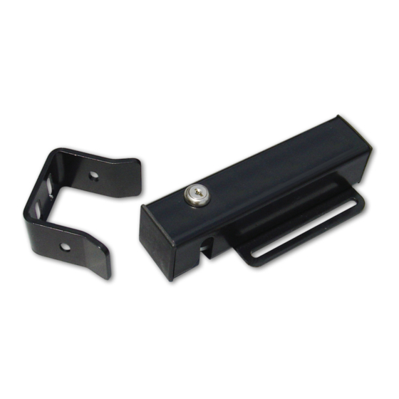
AUTOMATIC
GATE LOCK
Printed in China
®
Copyright © 2021 Nortek Security & Control LLC
Advertisement

Related Manuals for GTO FM143


Summary of Contents for GTO FM143
- Page 1 This manual shows two examples of the most common installations, and should provide insight into most other applications. If you have any questions during installation, please call (800) 543-1236 for technical support. FM143/FM144 Installation Manual Printed in China Copyright © 2021 Nortek Security & Control LLC...
-
Page 2: Parts Included
Bolts, washers, and nuts for the receiver. (see Illustration C, page 4) The installation has two parts: 1. Mounting The Lock and Lock Receiver 2. Connecting the Control Boards Once you have the necessary mounting hardware, you can begin the installation. FM143/FM144 Installation Manual [5/20/21]... - Page 3 Installing The Gate Lock NOTE: The Automatic Gate Lock can be installed on single and dual gate systems. Use the appropriate instructions for the system you have - SINGLE GATE (below) or DUAL GATES (page 5). Single Gate Installation Turn power switch OFF on the bottom of the control box. Disconnect gate opener by removing hairpin clip and clevis pin from the gate bracket end of the opener.
- Page 4 Remember to check the alignment and mark positions before drilling holes in fence post . Added cross member to support lock from Clevis Pin force of slammimg shut Lock Receiver Locking Cap U-bolts, saddles & nuts (not provided) FM143/FM144 Installation Manual [5/20/21]...
- Page 5 Dual Gate Installation Turn power switch OFF on the bottom of the control box. Disconnect gate openers by removing hairpin clip and clevis pin from the gate bracket end of the openers. Disconnecting the openers will allow the gates to swing freely during installation of the gate lock.
- Page 6 Keys are unique for security purposes and can not be replaced by Nortek Security & Control. A locksmith will be required if all copies of the keys are lost. FM143/FM144 Installation Manual [5/20/21]...
- Page 7 Wiring the Automatic Gate Lock Wiring the lock to MM371, MM372, MM571, MM572 and TS571 Operators NOTE: A wire jumper is required between ‘LOCK V-’ and ‘LOCK Relay Common’. CONTROL OUTPUTS POWER LOCK INPUT 2ND OPERATOR Wiring the lock to MM560, MM562, 18 VOLT Linear Pro 3000XLS and 4000XLS TRANSF.
- Page 8 Wiring the lock to MM360 Operators. CLOSE TIME NOTE: Dip switch 4 must be set to LOCK (OFF). LEARN LIMIT REMOTE PULL-PUSH MODE1 MODE2 LOCK/BEACON PULL-PUSH CHARGING MODE1 POWER MODE2 LOCK/BEACON LINK 18VAC AUX OUT SOLAR PANEL RCVR FM143/FM144 Installation Manual [5/20/21]...
- Page 9 Wiring the Lock to Gate Opener Control Boards Manufactured prior to 2006. Call Nortek Control Technical Support at (800) 543-1236 for verification if needed. Turn control box power switch OFF and unplug the transformer or disconnect the solar panel. Step 1: Remove control box cover and disconnect battery lead wires from the battery terminals before wiring the lock board to the opener control board.
-
Page 10: Troubleshooting
See the Gate Opener Installation Manual for information on obstruction settings. NOTE: Be sure your gate moves freely on its hinges without binding or dragging. FM143/FM144 Installation Manual [5/20/21]... -
Page 11: Limited Warranty
Mighty Mule, GTO, and Linear are wholly owned brands of Nortek Security & Control. Limited Warranty This product is warranted to the original consumer (“You”) by Nortek Security & Control LLC (“Nortek Control”) against defects in material and workmanship. This limited warranty only extends to You if You purchased directly from Nortek Control or through one of Nortek Control’s authorized sales partners. - Page 12 5919 Sea Otter Place • Carlsbad, CA 92010 • USA Phone: (800) 421-1587 ©2021 Nortek Security & Control LLC. All rights reserved. Mighty Mule, GTO Access Systems and Linear are registered trademarks of Nortek Security & Control LLC. 10024428 Rev-B...
Need help?
Do you have a question about the FM143 and is the answer not in the manual?
Questions and answers