Table of Contents
Advertisement
Quick Links
Chapter 1
Chapter 1
Introduction
K8S760M series of mainboards utilize SIS760+SIS964 chipset, providing
a fully compatible, high performance and cost-effective mATX platform.
The new integrated technologies, together with AC' 97 audio(6-channel),
8 USB 2.0, 2 SATA, 2 IEEE 1394 ports(optional)and ATA133/100/66/33,
give customers an advanced, multimedia solution at reasonable price. It
TM
TM
provides HyperTransport
technology to support AMD Athlon
64 Socket
754 processors and the DDR266/333/400 memory. It also provides ad-
vanced features such as Wake up by USB devices function. Suspending
to RAM(optional), the optimal implementation of the Advanced Configura-
tion and Power Interface (ACPI) specification, makes the PC' s power
consumption drop to the lowest possible level and enable quick wakeup.
K8S760M
1
Advertisement
Table of Contents

Related Manuals for Gigabyte K8S760M Series


Summary of Contents for Gigabyte K8S760M Series
- Page 1 Chapter 1 Chapter 1 Introduction K8S760M series of mainboards utilize SIS760+SIS964 chipset, providing a fully compatible, high performance and cost-effective mATX platform. The new integrated technologies, together with AC’ 97 audio(6-channel), 8 USB 2.0, 2 SATA, 2 IEEE 1394 ports(optional)and ATA133/100/66/33, give customers an advanced, multimedia solution at reasonable price.
- Page 2 Introduction Form factor mATX form factor of 244mm x 240mm Microprocessor Supports AMD Athlon 64 Socket 754 CPU Supports HyperTransport technology System memory Supports DDR266/333/400 SDRAM Supports 64/128/256/512Mb technology up to 2GB Provides two 184-pin DDR SDRAM interfaces Onboard IDE Supports Independent timing of up to 4 drives Supports Ultra ATA 33/66/100/133, PIO mode Two fast IDE interfaces supporting four IDE devices including IDE hard disks and CD...
-
Page 3: Advanced Features
Chapter 1 Advanced features PCI 2.3 Specification Compliant Provides Trend ChipAwayVirus On Guard Supports Windows 98/2000/ME/XP soft-off Supports Keyboard Password Power-on function(optional) Onboard SATA Two SATA devices including SATA HDD and CDROM/DVD ROM devices Supports 150Mbps transfer rate. BIOS Licensed advanced AWARD(Phoenix) BIOS, supports flash ROM, plug and play ready Supports IDE CDROM/USB boot up. - Page 4 Installation Instructions Chapter 2 Installation Instructions This section covers External Connectors and Jumper Settings. Refer to the mainboard layout chart for locations of all jumpers, external connectors, slots and I/O ports. Furthermore, this section lists all necessary connector pin assignments for your reference. The par- ticular state of the jumpers, connectors and ports are illustrated in the following figures.
-
Page 5: External Connectors
Chapter 2 External Connectors PS/2 Keyboard/Mouse Connector PS/2 keyboard connector is for the usage of PS/2 keyboard. If using a standard AT size keyboard, an adapter should be used to fit this connector. PS/2 mouse connector is for the usage of PS/2 mouse. PS/2 Mouse connector PS/2 Keyboard connector USB1, USB2;... -
Page 6: Installation Instructions
Installation Instructions Line-in jack, Microphone-in jack and Speaker-out jack The Line-in jack can be connected to devices such as a cassette or minidisc player to playback or record. The Microphone-in jack can be connected to a microphone for voice input. The Speaker-out jack allows you to connect speakers or headphones for audio output from the internal amplifier. -
Page 7: Reset Switch (Reset)
Chapter 2 ATX 12V Power Supply Connector & Power Switch (POWER Switch) The power switch (POWER SW) should be connected to a momentary switch. When powering up your system, first turn on the mechanical switch of the power supply (if one is provided), then push once the power switch. - Page 8 Installation Instructions Power LED Connector (PWR_LED) When the system is in S0 status, the LED is on. When the system is in S1 status, the LED is blink; When the system is in S3(optional),S4, S5 status, the LED is off. The connector has an orientation.
-
Page 9: Infrared Header (Irda)
Chapter 2 USB5,6; USB7,8 Besides USB1,2,3,4 on the back panel, K8S760M series of mainboards also have 10-pin headers on board which may connect to front panel USB cable( optional ) to provide addi- tional four USB ports. USB0- USB5_6 USB1-... - Page 10 Installation Instructions Audio Connectors (CD_IN, AUX_IN)(optional) CD_IN is Sony standard CD audio connector, it can be connected to a CD-ROM drive through a CD audio cable. AUX_IN allow you to receive stereo audio input from sound sources such as a TV tuner, or MPEG card. AUX_IN Left Audio Channel (optional)
- Page 11 Chapter 2 Front IEEE 1394 port(1394_1)(optional) Besides one 1394 port on the back panel, the mainboard also have one 10-pin headers on board to provide additional IEEE 1394 port. Ground 1394_1 12V(FUSE) 12V(FUSE) TPB- TPB+ Ground Ground TPA- TPA+ Onboard SATA The mainboard provides two Serial ATA connectors, SATA is a storage interface that is compliant with SATA 1.0 Specification.
- Page 12 Installation Instructions UART COM Connector(COM2)(optional) Besides COM1 on the back panel, the mainboard also supply another COM connector which connects with serial mouse, MODEM and other serial device. COM2 T X D D T R C T S R T S SPDIF OUT Connector(optional) The SPDIF output allow your digital audio input from digital audio devices.
-
Page 13: Jumper Settings
Chapter 2 SPDIF IN Connector(optional) SPDIF IN Cut away SPDIF_IN Jumper Settings Jumpers are located on the mainboard, the clear CMOS jumper JCC, enable keyboard password power-on function jumper JKB etc. Pin 1 for all jumpers are located on the side with a thick white line (Pin1→... - Page 14 Installation Instructions BIOS-Protection Jumper (BIOS_WP) The BIOS of the mainboard is inside the FWH. If the jumper BIOS_WP is set as closed, the system BIOS is protected from being attacked by serious virus such as CIH virus, you will be unable to flash the BIOS to the mainboard in this status. Flash Write Disabled BIOS_WP...
- Page 15 Chapter 2 Enable keyboard password power-on function (JKB)(optional) The mainboard provides the advanced keyboard password power-on function. Before using this function, set JKB with pin1 & pin2 closed. Otherwise, set JKB with pin2 & pin3 closed for disabling. Disable 1 2 3 Enable 1 2 3 Furthermore in order to implement this function, set “...
-
Page 16: Bios Description
BIOS Description Chapter 3 BIOS Description The mainboard uses AWARD BIOS Setup program that provides a Setup utility for users to modify the basic system configuration. The information is stored in CMOS RAM so it retains the Setup information when the power is turned off. This chapter provides you with the overview of the BIOS Setup. - Page 17 Chapter 3 AWDFLASH.EXE This is a flash memory write/read utility used for the purpose of upgrading your BIOS when necessary. Before doing so, please note: We strongly recommend you only upgrade BIOS when encounter problems. Before upgrading your BIOS, review the description below to avoid making mistakes, destroying the BIOS and resulting in a non-working system.
- Page 18 BIOS Description AWARD BIOS Description Entering Setup Power on the computer, when the following message briefly appears at the bottom of the screen during the POST (Power On Self Test), press <Del> key to enter the AWARD BIOS CMOS Setup Utility. Press <Del>...
- Page 19 Chapter 3 Integrated Peripherals The integrated peripherals setup allows user to configure the onboard IDE controller, floppy disk controller, the printer port and the serial ports etc.. PC Health Status The PC health status display CPU and case fan speed. Set Supervisor/User Password Changes, sets, or disables password.
- Page 20 Appendix Appendix QDI Utility CD A QDI Utility CD is supplied with this mainboard, the contents contained in it are showed as below: 1. Driver Install Using this choice, you can install all the drivers for your mainboard . You should install the drivers in order, and you need to restart your computer until all the drivers are installed.
- Page 21 Appendix LogoEasy II(optional) LOGOEASY II supports the high-resolution 640x480 or 800x600 image display and full- screen, top right corner or bottom right corner display. It also supports simultaneous display of logo and sign-on message of the BIOS testing system. LOGOEASY II is a tool that can be operated in multi-platforms to refresh and change LOGO graphics including DOS, WINDOWS 9X, WINDOWS NT, WINDOWS ME and WINDOWS XP.
- Page 22 Appendix Cool'n'Quiet Technology(optional) Cool'n'Quiet Technology is an innovative solution available on AMD Athlon 64 proces- sor-based systems that allows the system to dynamically and automatically select the CPU speed, Voltage and Power combination that match the instantaneous user perfomance need. Follow the steps exactly for a successful installation: 1.
- Page 23 Appendix QDI BootEasy(German) BootEasy ist eine Neuentwicklung von QDI, die neue Innovation der QDI Easy- Technologien. Mit der BootEasy- Technologie Technik wird der Bootvorgang nur noch vier bis fü nf Sekunden in Anspruch nehmen, bis das Betriebssystem geladen wird. Der Grund fü r die lange Warterei liegt in den Routine-Abfragen, die das BIOS bei jedem Start abarbeitet.
- Page 24 Appendix Instalación de la placa base QDI K8S760M(Spanish): Asegú rese que se incluyen los siguientes artí culos: Placa base QDI K8S760M, 1 cable de datos para el puerto IDE y 1 cable de datos para el Floppy, jumpers, 1 manual de usuario QDI K8S760My un disco compacto con los controladores de la placa base QDI K8S760M.
-
Page 25: Instalación Del Sistema
Appendix Instalación del sistema: Encienda su equipo mediante el interuptor de encendido de la caja. Presione la tecla « Supr » para entrar en el menú de configuració n de la BIOS. Seleccione los valores de la Bios en concordancia con la configuració n de su sistema (Nosotros le recomendamos que deje los valores establecidos por la Bios por defecto, para evitar posibles fallos que ocasionen que su sistema no funcione correctamente). - Page 26 Appendix Manuel d’ installation des cartes mè res de la sé rie QDI K8S760M (French): Inté gration du systè me : Vé rifier la pré sence de chaque é lé ment dans la boite de la carte mè re de la sé rie QDI K8S760M : Une carte mè...
-
Page 27: Installation Du Système
Appendix que le liseré rouge de ces derniè res correspond à l’ emplacement de la broche numé ro 1 du connecteur. Connecter les câ bles de l’ unité centrale de l’ ordinateur sur les broches inté gré es à la carte mè... - Page 28 Appendix Lors de son achat un CD-ROM d’ installation QDI est livré avec la carte mè re de la sé rie QDI K8S760M. 1. Driver Install : Avec cette option, il est possible d’ installer les pilotes de la carte mè re de la sé rie QDI K8S760M aisé...
- Page 29 Appendix QDI K8S760M installazione mainboard (Italian): 1. Assicurarsi che la scatola sia completa: QDI K8S760Mmainboard, cavo IDE e Floppy, jumpers, manuale dell’ utente della mainboard QDI K8S760M e cd-rom drivers. 2. Controllare che il cavo alimentazione proveniente dal computer-case sia sconnesso assicurarsi inolre di aver indossato corretamente il bracciale da polso collegato a massa.
- Page 30 Appendix Dopo questo ultimo passo procedere all’ installazione dei driver delle varie periferiche IL CD CONTENENTE I DRIVER DELLA VOSTRA MAINBOARD QDI E’ CONTENUTO NELLA SCATOLA Installazione driver E possibile installare tutti i driver della Vs. mainboard in modo facile e veloce. Dovreste installare i driver nella seguente succesione, finito cio’...
-
Page 31: Installing The Audio Driver
Appendix Using 4-/6-Channel Audio(4-/6- Channel Audio Interface) The motherboard is equipped with Realtek ALC655 chip, which provides support for 6- channel audio output, including 2 Front, 2 Rear, 1 Center and 1 Subwoofer channel. ALC655allows the board to attach 4 or 6 speakers for better surround sound effect. The section will tell you how to install and use 4/6-channel audio function on the board. -
Page 32: Digital Audio Output
Appendix 6-Channel Analog Audio Output Line Out(Rear Channels) Line Out (Front channels) Line Out(Center & Subwoofer Channels) Description: Both Line In and MIC are converted to Line Out function under 6- channel configuration. Digital Audio Output Coaxial SPDIF jack Description: Connnet the SPDIF speakers to the Coaxial SPDIF jack. -
Page 33: Selecting 4- Or 6-Channel Setting
Appendix Selecting 4- or 6-Channel Setting 1. Click the audio icon from the window tray at the bottom of the screen. 2. Select any surround sound effect you prefer from the “ Environment” pull-down menu under the Sound Effect tab. Click here and the pull- down menu will appear 3. -
Page 34: Testing The Connected Speakers
Appendix 4. The following window appears. Headphone Output 2 Channels Output 4 Channels Output Keep UnSelect 6 Channels Output Status 5. Select the multi-channel operation you prefer from No. of Speakers. 6. Click OK Testing the Connected Speakers To ensure 4- or 6-channel audio operation works properly, you may need to test each connected speaker to make sure every speaker work properly. -
Page 35: Playing Karaok
Appendix Playing KaraOK The KaraOK function will automatically remove human voice (lyrics) and leave me-lody for you to sing the song. The function is applied only for 2-channel audio opera- tion, so make sure channel mode is selected in the “ No. of Speakers” column before playing KaraOK. -
Page 36: Cpu Installation Procedures
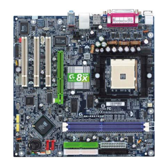
Appendix CPU Installation Procedures 1. Pull the lever sideways away from the socket. Then, raise the lever up to a 90-degree angle. 2. Look for the cut edge. The cut edge should point towards the lever pivot. The CPU will only fit in the correct orientation. - Page 37 Board Layout of K8S760M Note: The layout includes all options. It is for your reference only.
- Page 38 Top :Line in Midd: Spk out Top :PS/2 Mouse Bttm:Mic in Bttm:PS/2 Keyboard COM1 Top :1394 Top :LAN(option) Bttm:USB1,2 Bttm:USB3,4 Top :LAN Bttm:USB0,1 JUSB BIOS_WP IrDA INTR North Bridge Socket 754 JFUSB DIMM1 South Bridge DIMM2 IDE2 SATA1 SATA2 SYS_FAN IDE1 ATXPWR Note: pin1 for a jumpers are located on the side with black line.