Advertisement
Quick Links
ASSEMBLY & INSTALLATION INSTRUCTIONS
Focal Point Fires Ltd
Christchurch,Dorset BH23 2BT
Tel:01202 499330
Fax:01202 499326
www.focalpointfires.co.uk
e :sales@focalpointfires.co.uk
Focal Point Fires Ltd
RBK House, Irishtown, Athlone,
Co. Westmeath, N37 XP52,
Ireland Tel: 01202 499330
Fax: 01202 499326
www.focalpointfires.co.uk
e: sales@focalpointfires.co.uk
Please note : Except where otherwise stated, all rights, including copy
right in the text, images and layout of this booklet is owned by Focal
Point Fires Ltd. You are not permitted to copy or adapt any of the con
tent without the prior written permission of Focal Point Fires Ltd.
MODELS COVERED BY THESE INSTRUCTIONS
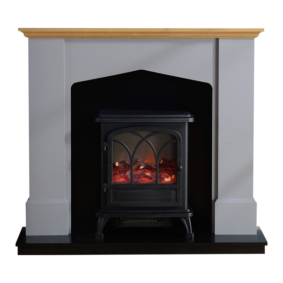
HURST SUITE
All instructions must be handed to the user for
safekeeping.
Revision B - 03/21
©
2021
Focal Point Fires Ltd.
Advertisement

Related Manuals for FocalPoint HURST SUITE


Summary of Contents for FocalPoint HURST SUITE
- Page 1 ASSEMBLY & INSTALLATION INSTRUCTIONS MODELS COVERED BY THESE INSTRUCTIONS HURST SUITE Focal Point Fires Ltd Christchurch,Dorset BH23 2BT Tel:01202 499330 Fax:01202 499326 www.focalpointfires.co.uk e :sales@focalpointfires.co.uk Focal Point Fires Ltd RBK House, Irishtown, Athlone, Co. Westmeath, N37 XP52, Ireland Tel: 01202 499330 Fax: 01202 499326 www.focalpointfires.co.uk...
-
Page 2: Hardware & Parts List
� Section Contents Page No. Important notes Tools required Hardware & parts list Assembly Installation Cleaning/finishing Guarantee - terms and conditions To ensure safe and stable installation: I. The assembled Fire Surround can be fixed / secured to wall. 2. The wall must be sturdy and in good repair. 3.Some walls require alternative fixings (not included). - Page 3 • � ® ® ® ® ® • ® ® �.O ASSEMBLY STEP I © © � With a cross headed screw driver insert 2x single head cam bolts (A) into the inner left leg (7) and the inner right leg ( 8 ) .
- Page 4 STEP 2 Ax 5 ® Next select the fro nt centre piece (9) and insert I x 8x40mm wooden do wels (C) into the top end, also using a small amount of glue (not pro vided). With a cro ss headed screw driver insert Sx single headed cam bo lts (A) into the correct holes in the rear.
- Page 5 STEP 4 � ,� ®� ® � � With a cross headed screw driver screw 3x single headed cam bolts (A) into position on the rear of the front left leg (5). Including a small amount of glue insert the 2x 8x40mm wooden dowels (C) into the top and bottom ends of the front left leg (5).
- Page 6 STEP 6 G x 10 With the front left leg (5) and the front right leg (6) laid out in the correct position, carefully place the sub assembly previously made onto of the rear of both the left and right hand legs (5,6). Line all I Ox screw holes in the top sub assembly and both legs (6,5). Once lined up screw I Ox 3.5x25mm screws (G) with a cross headed screw driver from the rear to secure together.
- Page 7 STEP 8 ® Insert 4x 8x40mm wooden dowels (C) with some glue into the end of the right hand leg (3). STEP Line the 8x40mm wooden dowels (C) on the left and right hand legs (2,3) with the dowel holes in the sub assembly. Also inserting the 6x single headed cam bolts (A) from the sub assembly into the left and right hand legs (2,3).
- Page 8 STEP 10 AX 10 Insert I Ox single headed cam bolts (A) with a cross headed screw driver into the underside of the top panel (I). STEP 11 Insert all I Ox cam bolts (A) on the top panel into the top of the cam bolt holes of the surround. Once pushed home, insert I Ox cam locks (B) into the surround, then tighten into position with a cross headed screw driver.
- Page 9 STEP 12 Insert 2x 8x 40mm wooden dowels (C) with som e glue into the end of the top rebate ( I I). With a cross headed screw driver insert 2x cam bolts (A) into the correct positions. STEP 13 Insert 4x 8x 40mm wooden dowels (C) into the ends of the side rebates ( I 0) repeat this process for the opposite side rebate ( I 0).
- Page 10 STEP 14 ® --,:,- , �: Stand both side rebates ( I 0) on their ends, with the 8x40mm wooden dowels (C) facing up. Offer the top rebate ( I I) to the side rebates ( I 0), inserting the single headed cam bolts (A) into the holes in side rebates (10). Insert the cam locks (B) into the side rebates (10) and tighten with a cross headed screw driver.
- Page 11 STEP 16 AX 10 BX 10 With a cross headed screw driver insert 10x singe headed cam bolts into the hearth (4). Carefully lift the suite onto the hearth (4) ensuring that all 10x cam bolts (A) insert into the bottom of the suite correctly. Once in the correct position, insert 10x cam locks (B) into the suite and tighten with a cross headed screw driver.
- Page 12 STEP � IX 2 To avoid splitting the rear of the suite pre drill the holes. Now attach the fixing strap (I) to the rear of the suite using the ( D ). 4x12mm screws STEP 2 ✓ Once the fixing straps are in position, centre and level the suite into its final fitting position. Mark with a pencil on the wall where you wish to drill.
- Page 13 Before carrying out any of the following operations, ensure that the appliance is OFF and completely cold. Regularly clean around the appliance to ensure that dust, fluff, pet hair etc, are kept to a minimum. There are no other specific requirements for care, other than regular cleaning of the general appliance.
Need help?
Do you have a question about the HURST SUITE and is the answer not in the manual?
Questions and answers