Advertisement
Advertisement
Table of Contents

Subscribe to Our Youtube Channel
Related Manuals for FocalPoint Hurst Suite

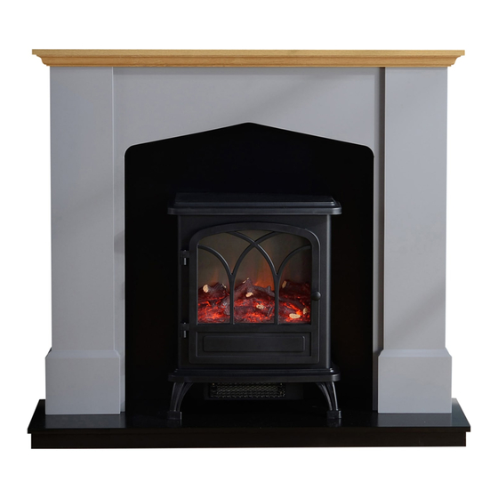
Summary of Contents for FocalPoint Hurst Suite
- Page 1 F 11...
- Page 2 GB IE A S S E M B L Y I N S T R U C T I O N S Section Contents Page No. Important notes Tools required Hardware & parts list Assembly Installation Cleaning/ finishing Guarantee - terms and conditions 1.0 IMPORTANT NOTES 2.0 TOOLS REQUIRED Cross head screwdriver PZ2 (3 inches in length or greater)
- Page 3 3.0 HARDWARE & PARTS LIST - CONTINUED GB IE CODE NAME FIGURE QUANTITY CODE NAME FIGURE QUANTITY RIGHT INSIDE WALL PLUGS 2PCS 1PCS ⑧ PANELS (6X30mm) LEFT INSIDE ⑨ 1PCS ALLEN KEY 1PCS PANELS GLUE ⑩ 1PCS HEARTH 1PCS (10g) BACK 2PCS 1PCS...
- Page 4 GB IE 4.0 ASSEMBLY - CONTINUED STEP 3 Fixings Parts A x 4 PCS B x 6 PCS C x 6 PCS ⑤ ② ③ ⑥ ④ Insert some glue (J) into the 4 x dowel holes in the right leg (4) and left leg (3). Insert the 4 x wooden dowels (A) into the right leg (4) and left leg (3).
- Page 5 GB IE 4.0 ASSEMBLY - CONTINUED Fixings Parts STEP 5 ③ A x 4 PCS B x 6 PCS ② C x 6 PCS ⑤ ④ ⑦ ⑨ ⑧ ⑥ ⑩ Firstly insert 4 x wooden dowels (A) with glue (J) into the top of the hearth (10). With a cross headed screw driver, carefully insert 6 x single headed cam bolts (C) into the top of the hearth (10).
- Page 6 GB IE 4.0 ASSEMBLY - CONTINUED STEP 7 Fixings Parts A x 5 PCS B x 6 PCS ① ③ ⑤ ② ④ ⑦ ⑨ ⑥ ⑧ ⑩ Insert all 3 x cam locks (B) into each leg. The dowel joints (A) need to be glued in at each end of the surround. Connect the top mantle to the surround, making sure all 6 x inserts are in their correct position.
- Page 7 STEP 1 Fixings Parts G x 2 PCS K x 2 PCS G x 2 K x 2 To avoid splitting the rear of the surround, pre drill the holes, Then attach the fixing straps (K) to the rear of the surround using the 4x12 screws (G) Fixings Parts...
Need help?
Do you have a question about the Hurst Suite and is the answer not in the manual?
Questions and answers