Table of Contents
Advertisement
Quick Links
Deva018 Single Axis Sine-Wave Interpolator User's Manual
V2.0
SIGNAL CONVERSION & GENERATION
Deva018 Sine-Wave Interpolator User's Manual
CONTENTS:
•
Overview
•
Installation and Usage
Deva Electronic Controls Limited | 52 Woodside Business Park | Birkenhead | Wirral | CH41 1EL
Phone:
+44 (0)151 647 3222
| Fax:
+44 (0)151 647 4511
For additional downloadable Support
Documentation, please visit
www.deva.co.uk/support-downloads
Or contact us at
| Email:
| Website:
sales@deva.co.uk
SUPPORT:
support@deva.co.uk
www.deva.co.uk
Advertisement
Table of Contents

Related Manuals for DEVA Deva018

Summary of Contents for DEVA Deva018
- Page 1 • Installation and Usage Documentation, please visit www.deva.co.uk/support-downloads Or contact us at support@deva.co.uk Deva Electronic Controls Limited | 52 Woodside Business Park | Birkenhead | Wirral | CH41 1EL Phone: | Fax: | Email: | Website: +44 (0)151 647 3222 +44 (0)151 647 4511 sales@deva.co.uk...
- Page 2 © Deva Electronic Controls Ltd 2021 All information within this document is given in good faith by Deva Electronic Controls Ltd. Deva Electronic Controls Ltd shall not be liable for any loss or damage, howsoever arising, that may be attributed to errors within, or omissions from, this document, nor for the use of, or application of, the information provided herein.
-
Page 3: Table Of Contents
Deva018 Single Axis Sine-Wave Interpolator User’s Manual Contents Overview ..................1 About this Manual ..................1 Deva018 Features ..................1 1.2.1 Facilities ..........................1 Installation and Usage ..............3 Connections ....................3 Test point connector ..................4 Configuration Solder Pads ................4 2.3.1... -
Page 5: Overview
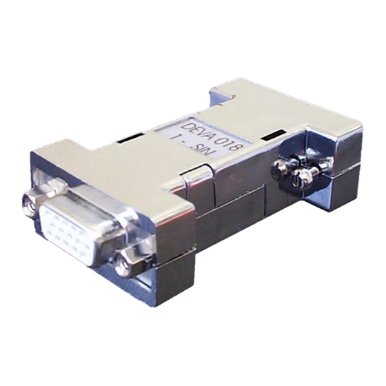
Deva018 Features The Deva018 Single Axis Sine Wave Interpolator has been designed for use in motion and control applications using a PC based system. It can be used for a wide range of applications, such as manual Coordinate Measuring Machines (CMMs), automation and process control, control system diagnostics, metrology and data acquisition. -
Page 7: Installation And Usage
125kHz and the maximum output count rate is 5MHz using x10 interpolation. The Deva018 operates from +5V, which may be supplied either from the input or output connector. The output connector is pin to pin compatible with all Deva’s encoder interface and motion control products. -
Page 8: Test Point Connector
0V. In test mode pins 1,2,6 & 7 of the output connector will provide the buffered A and B signals. All four outputs should be 0.5Vpp and biased around 2.5V. Important : Do not connect the Deva018 to the target controller when test mode is enabled. The test connections shown above are recommended. -
Page 9: Example Settings
Deva018 Single Axis Sine-Wave Interpolator User’s Manual Installation and Usage Pads CFG0 and CFG1 control the Interpolation factor. CFG1 CFG0 Factor x100 Pads CFG2 and CFG3 control the input level. -
Page 10: 018-Brk1 Breakout Test Board For 018 Setup
The 018-BRK1 test board pictured in Figure 2.2 is available to assist in making test connection to the Deva 018-1SIN interpolator (Order Code 018-BRK1). It is inserted in the cable after the 018-1SIN and derives power from the Deva001, Deva004 or Deva037 in use. - Page 12 For additional downloadable Support Documentation, please visit www.deva.co.uk/support-downloads Or contact us at support@deva.co.uk Deva Electronic Controls Limited | 52 Woodside Business Park | Birkenhead | Wirral | CH41 1EL Phone: | Fax: | Email: | Website: +44 (0)151 647 3222 +44 (0)151 647 4511 sales@deva.co.uk...
Need help?
Do you have a question about the Deva018 and is the answer not in the manual?
Questions and answers