Table of Contents
Advertisement
Quick Links
Advertisement
Table of Contents

Related Manuals for SOC Robotics MM130

Summary of Contents for SOC Robotics MM130
- Page 1 MM130 Technical Reference Manual MM130 Single Axis Stepper Motor Driver 1/16 Microstepping 3A Unipolar Driver Technical Reference Manual PCB Rev 1.1 Motor Control Software Version 1.00 www.soc-robotics.inc © Copyright 2010. SOC Robotics, Inc. Manual Revision 1.01 June 2010...
-
Page 2: Warranty Statement
No goods may be returned to SOC Robotics without SOC Robotics Returned Material Authorization form. Prior to any return of goods by Buyer pursuant to this Section, Buyer shall afford SOC Robotics the opportunity to inspect such goods at Buyer’s location, and any such goods so inspected shall not be returned to SOC Robotics without its prior written consent. -
Page 3: Table Of Contents
Software Operation …………………………………………….……….………..16 4.1 Theory of Operation…………………………...…...……………………………….…..…16 4.2 Auxiliary IO……..……………………….…………..………………….…………….….…16 4.3 Step Drive Connector ………...……..……………………………………………………16 4.4 Driver Commands.…………………….……..……………………….……………..….…17 4.5 MM130 Command Overview .……………..………………………………………..……18 4.6 Detailed Command Description…………………..………………………………………21 Electrical and Mechanical Description …………………………..….……30 5.1 Component Layout…………………………………………………………………...……30 5.2 Electrical Specifications……………………………………………………………...……30 5.3 Mechanical Dimensions ……………………………………………….…………….……30 Circuit Schematics ………………………………………………………..……31... -
Page 4: Introduction
I2C port. The MM130 can operate as a single axis G Code processing system by acting on commands sent to it via the I2C or Step/Direction input lines. See the section on software operation for a full description of the complete command structure. - Page 5 It is a good idea to wire a fuse between the motor power supply and the MM130. Try not to turn motor power on if the logic side of the MM130 is not turned on.
- Page 6 The MK4 is an excellent choice to attach up to four MM130’s to a PC’s parallel port and be controlled using Mach3. MK4 Controller ©...
- Page 7 MM130 Technical Reference Manual The MK14 is a USB 2.0 version of the MK4 with an onboard processor that accepts up to four MM130 drivers. The MK14 has four aux open collector outputs and five limit switch inputs all read via the parallel port.
- Page 8 The MK200 is a high end DSP based G Code processing platform with built-in vision processing that is capable of driving the MM130’s at their maximum rate of 80,000 microsteps/second. The MK200 is intended for high end applications that require extremely fast stepper motor operation and/or real time vision processing.
-
Page 9: Detailed Description
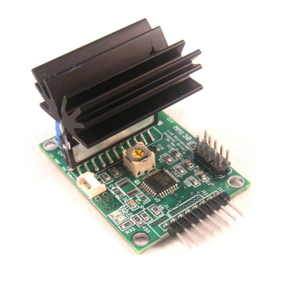
Figure 2-1. Primary Components on top and bottom sides of PCB. 2.2 Processor The MM130 has an 8bit RISC AVR processor (ATmega168) running at 20MHz. Note that the Atmega168 requires 5VDC to run at 20MHz. The program running in the Atmega168 monitors the step/direction input lines and drives the SLA7078 microstepping driver chip. -
Page 10: Twi Port
2.5 ISP Programming Port The MM130 has two ISP programming ports – a 4 pin Molex connector and a 6 pin header. The MM130’s Flash can be programmed by attaching a 4 line cable from the MK4 programming port to the Molex connector. -
Page 11: Molex Connector
The MM130 can be controlled directly by the USB10, MK1, MK4, MK4USB, MK54 and MK200. The MK4 attaches to a PC parallel port and provides an attachment point for up to four MM130’s. The MK4 also supporst limit switch inputs and EStop. The MK4USB is a version of the MK4 that has a USB 2.0 interface to allow direct communication between each attached MM130 and a host PC for both motion control such as step/direction and configuration control such as changing step mode. -
Page 12: Applications
Ant6 6 Channel H-Bridge Controller 2.8 Applications The MM130 is a unipolar stepper motor controller that responds to step and direction signal inputs but is also able to communicate with other smart controllers via the I2C interface. In fact, large numbers of MM130’s can be ganged together and be controlled via a single I2C master. -
Page 13: Hardware Expansion Port Summary
3.0 MM130 Hardware Expansion Port Summary 3.1 Introduction The MM130 has three I/O ports: a motor control port, programming port and an auxiliary IO port as shown in the connector layout diagram below. Two alternative configurations of the board are available: Configuration 1 replaces the 0.1”... -
Page 14: Motor Control Port
The auxiliary IO port accepts analog input, digital IO and step/direction inputs. The digital IO can be used to connect external sensors such as rotary and linear position sensors or to allow the MM130 to control external devices such as relays. The analog inputs allow the MM130 to measure external analog sensors. The current software release does not support this functionality but is planned for the next release. -
Page 15: Twi I2C Expansion Port
Figure 3-5. TWI I2C Port with 4 Pin Molex picoBlade Connector. 3.5 ISP Programming Port The MM130 has two ISP Programming ports – a six pin header compatible with the Atmel 6 pin header ISP programming standard and a four pin picoBlade Molex connector compatible with the USB10U, MK4, MK14, MK54 and MK200 controllers. -
Page 16: Software Operation
4.0 Software Operation 4.1 Theory of Operation The MM130 is driven by step and direction signals applied to connector J10. The MM130 is shipped with quarter step mode enabled. The MM130 supports full, wave, half, quarter, one eighth and one sixteenth step modes. -
Page 17: Driver Commands
Step and Direction lines. A bi-directional communication utility provides a real time link with MM130 processor allowing dynamic change and update of system parameters on the fly. An API library is available to provide application developers access to the configuration features of the new software. -
Page 18: Mm130 Command Overview
4.5 MM130 Command Overview The MM130 processor responds to commands sent to it via the Step/Direction signal lines. Using a simple encoding procedure it is now possible to communicate with the Motor Controller via the Step, Direction and Limit switch lines. - Page 19 A few of the command functions can be halted by entering the character sequence cxq. If the control software driving the MM130 does not need to support command mode then for increased reliability in noisy environments command recognition mode can be disabled by sending the command mode disable command cxcci.
- Page 20 – Toggle back and forth – all step modes, hit any key to exit x – Ramp low to high – high to low – all step modes, hit any key to exit © Copyright 2010. SOC Robotics, Inc. Manual Revision 1.01...
-
Page 21: Detailed Command Description
4.6 Detailed Command Description Step Mode Command Set the driver step mode. The MM130 is a microstepping unipolar stepper motor driver capable of full, half, quarter, eight and one sixteenth microstepping. s – Change Step Mode, 1-Full, !-FullF, 2-Half, @-HalfF, 4-Quarter, 8-Eight, 6-Sixteenth Set the driver step mode. - Page 22 If the setup and hold times for command recognition on the step/direction lines can not be guaranteed then the MM130 may accidently enter command mode. This can also happen if there is excessive noise on the step/direction signal lines.
- Page 23 After a step operation completes holding torque can be activated or deactived. If activated torque the time hold torque is applied can be set. The time duration is set in 0.1 second increments from a 1/10 of a © Copyright 2010. SOC Robotics, Inc. Manual Revision 1.01...
- Page 24 – Go to Home position, n-near side, f-far side, o-offset (float) i - Set feed rate (ipm), float s – Set step rate (pps), float p – Pause execution (msec), int c – Step clockwise © Copyright 2010. SOC Robotics, Inc. Manual Revision 1.01 June 2010...
- Page 25 Set the step rate in pulses per second (ppm). This command sets the step rate based on the number of steps per second. The parameter is entered as an integer or floating point number. Example: cxds125; - Set step rate to 125 steps per second. © Copyright 2010. SOC Robotics, Inc. Manual Revision 1.01 June 2010...
- Page 26 2000 steps at max rate and loop 4 times - Ramp using quarter step, 10 steps at each ramp cxdx410;20000;14; increment, 20000 steps at max rate and loop © Copyright 2010. SOC Robotics, Inc. Manual Revision 1.01 June 2010...
- Page 27 This command causes the drive to step the motor in the clockwise direction for a defined number of steps and then step in a counterclockwise direction the same number of steps at a pre-defined pps rate starting © Copyright 2010. SOC Robotics, Inc. Manual Revision 1.01...
- Page 28 The return status command indicates the status of the processor as either busy or not busy. If commands are sent to the MM130 without regard for the time it © Copyright 2010. SOC Robotics, Inc.
- Page 29 – Return controller busy status, b-busy, n-not busy Return the driver busy status. If the MM130 is busy executing a command or function then the get busy command will return a ‘b’ – if the driver is not busy then ‘n’ is returned.
- Page 30 Mode Record Commands The processor on the MM130 has approximately 1900 bytes of EEPROM storage space that can be loaded with a sequence of commands. For example, if the stepper motor needs to execute a sequence of commands to generate a specific motion turning on recording will store the commands as they are executed.
-
Page 31: Electrical And Mechanical Description
5.2 Electrical Specifications Electrical Input power: 5VDC @ 20ma Mechanical Dimensions: 2.12x1.58 in (one mounting hole) Weight: 38 grams 5.3 Mechanical Dimensions Board dimensions are stated in inches. © Copyright 2010. SOC Robotics, Inc. Manual Revision 1.01 June 2010... -
Page 32: Circuit Schematics
MM130 Technical Reference Manual 6.0 MM130 Circuit Schematics © Copyright 2010. SOC Robotics, Inc. Manual Revision 1.01 June 2010... - Page 33 MM130 Technical Reference Manual © Copyright 2010. SOC Robotics, Inc. Manual Revision 1.01 June 2010...
- Page 34 MM130 Technical Reference Manual © Copyright 2010. SOC Robotics, Inc. Manual Revision 1.01 June 2010...
- Page 35 MM130 Technical Reference Manual Notes: © Copyright 2010. SOC Robotics, Inc. Manual Revision 1.01 June 2010...
Need help?
Do you have a question about the MM130 and is the answer not in the manual?
Questions and answers