Table of Contents
Advertisement
Quick Links
Advertisement
Table of Contents

Related Manuals for Pentair Aurora 382 SC Series


Summary of Contents for Pentair Aurora 382 SC Series
- Page 1 Part # A-03-369 | © 2015 Pentair Ltd. | 07/06/15 1 ...
-
Page 2: Operational Limits
Warning: Electrical Shock Hazard This manual contains important information about the installation, handling, operation and safe use of Pentair All electrical connections are to be made by a qualified vertical in-line pumps. This information should be given to electrician in accordance with all codes and ordinances. -
Page 3: Pump Location
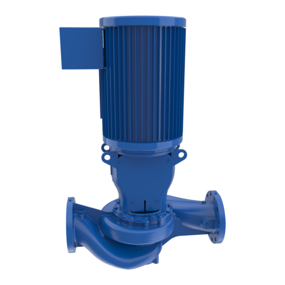
PRODUCT DESCRIPTION position. Ensure that the following precautions are taken for pumps being stored for more than six months. CONFIGURATION: Pump surfaces which are machined and unpainted (e.g. • Pumps are offered with various Mechanical seal types flange ends, feet mounting etc.) and are easily subjected available. - Page 4 Use following procedure for lifting the pump set. i. Remove the coupling guard ii. Place lifting straps/slings on each side of coupling through the motor bracket as shown in the FIG.3. iii. Use spreader bar in between the slings if necessary. This would be helpful for protecting the motor fan cover while lifting.
- Page 5 FIG.8A FIG.6 PIPE SUPPORTS: (Models 10x10x19, 10x10x14, 12x12x14, 12x12x18, 14x14x15 and 14x14x18 Only) For ease of installation and increasing rigidity of the unit, a Structural support may be provided at the pump suction and discharge ports with Isolation pads beneath the support, as illustrated in FIG.7.
-
Page 6: Operation
SHUT DOWN: Air leak/trapped in suction piping is one of the major cause of It is advisable to close the discharge valve before stopping the erratic pump performance. To avoid any such kind of trouble, pump to avoid any water hammer effect. However, this suction piping should be arranged on such a manner that there practice is not mandatory and pump may be stopped with are no high spots. -
Page 7: Mechanical Seal
MECHANICAL SEAL CONSUMABLES: The mechanical seal require flushing which is flushed from Following items are of regular use during preventive & discharge of the pump through a flush line. A throttle bush accidental maintenance and must be kept in stock by the isolates the mechanical seal from the liquid in the pump. -
Page 8: Mechanical Seal Replacement
REPAIRS (in inches) READ AND UNDERSTAND ALL SAFETY WARNINGS AT THE BEGINNING OF THE MANUAL BEFORE Motor Bracket - BEGINNING INSTALLATION OR ANY REPAIR 1-1/8 open end Hex Bolt motor mounting WORK wrench flange side This repairs section is broken into two parts. The first part Motor Bracket - covers the replacement of the mechanical seal. -
Page 9: Replacing The Mechanical Seal
Remove the two annular (round) keys (#46 & #47) as so the gap between the coupling halves is even. well as the two linear (square) keys (#53 & #54). Tighten the socket head cap screws in a crosswise pattern to the torque listed in the table below. Carefully lower the shaft impeller assembly by backing off on the two gland supporting wing nuts until the face SPLIT COUPLING BOLT TIGHTENING TORQUE... - Page 10 FIG. 12 FIG. 15 Remove the coupling guards (#17) by removing the four Remove the two linear (square) keys (#53, #54). (per side) cap screws (#18). Loosen the ferrule nuts on the tubing connectors (#1) and remove the gland flushing Motor key tubing (#3).
- Page 11 15. Clean all surfaces of the gland, checking for nicks and 24. Place the other half of the split coupling onto the shafts. sharp edges that may damage the elastomers on the Replace the six/four socket head cap screws (three/two mechanical seal or the gland.
- Page 12 rests on the wing nuts. Tighten the wing nuts on studs in such a way that jacking plate makes a firm contact with the bottom of the retaining ring (41A). Gland removed through gap between shafts Jacking plate in contact with retaining ring FIG.
- Page 13 utilize the wing nuts to raise the shaft (with impeller) upward until the step inside the coupling touches motor First time – Tighten to 50% of the specified shaft end face so that pre specified distance between torque pump shaft & motor shaft is maintained. Second time –...
- Page 14 Lift the rotating assembly from the casing. Pull the motor up and away utilizing suitable lifting equipment. Unscrew impeller screw (#9) and remove impeller seal (#9C). Remove the lower snap ring ((#41B) from the pump shaft. 10. Slide impeller (#11) and impeller key (#12) from shaft. Remove the cap screws (#5) and washers (#9A) holding 11.
- Page 15 MODEL 382A SC P-Base-Motor (1.5x1.5x9B, 2.5x2.5x7, 2.5x2.5x9, 2x2x12, 2x2x7, 2x2x9A/B/C, 3x3x12, 3x3x7A/B, 3x3x9A/B, 3x4x9, 4x4x11, 4x4x12, 4x4x7A/B, 4x4x9A/B, 4x5x9, 5x5x11, 5x5x12, 5x5x9, 6x6x11, 6x6x12, 6x6x9, 8x8x11, 8x8x12, 8x8x15, 10x10x15) FIG. 32 15 ...
- Page 16 MODEL 382B SC VERTICAL IN-LINE PUMP TC-Motor (Model 10x10x19) FIG.33 16 ...
- Page 17 MODEL 382B SC VERTICAL IN-LINE PUMP TC-Motor (Models 10x10x14, 12x12x14, 12x12x18, 14x14x15 and 14x14x18) FIG. 34 17 ...
- Page 18 PART LIST FOR 382 SC VERTICAL INLINE PUMPS Reference: FIG.32,33,34 (Exploded Views) ITEM NO. DESCRIPTION COMP. ELBOW COMP. CONNECTOR TUBING PIPE PLUG PIPE PLUG CAP SCREW WASHER CASING WEAR RING GASKET IMPELLER SCREW WASHER CAP SCREW SEAL JACKING PLATE IMPELLER IMPELLER KEY IMPELLER BUSH WEAR RING...
-
Page 19: Warranty
WARRANTY Seller warrants equipment (and its component parts) of its own manufacture against defects in materials and workmanship under normal use and service for one (1) year from the date of installation or start-up, or for eighteen (18) months after the date of shipment, whichever occurs first.
Need help?
Do you have a question about the Aurora 382 SC Series and is the answer not in the manual?
Questions and answers