Cosa 9610 Installation, Operation And Maintenance Manual
General purpose & explosion proof
Hide thumbs
Also See for 9610:
- Installation, operation and maintenance manual (51 pages) ,
- Installation, operation and maintenance manual (75 pages)

Related Manuals for Cosa 9610


Summary of Contents for Cosa 9610
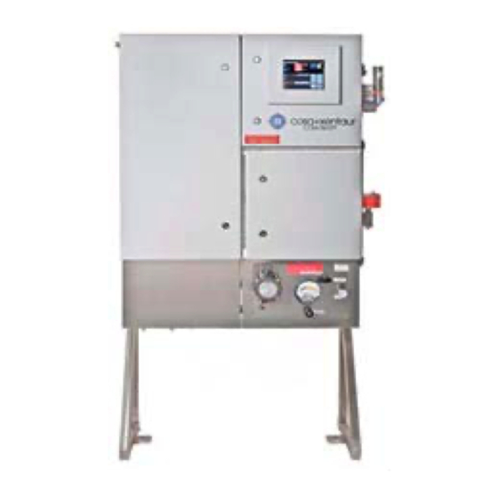
- Page 1 INSTALLATION, OPERATION MAINTENANCE MANUAL COSA 9610™ GENERAL PURPOSE & EXPLOSION PROOF Version: 1.3.3 Software version: 2.3.0.0 Revision date: August 17, 2009 Print date: 08/17/09...
- Page 2 COSA Instrument Corporation reserves the right to revise or to improve the design or specifications of the COSA 9610™ at any time and without notice.
-
Page 3: Table Of Contents
TORAGE 2.3. P .................. 12 LACEMENT 2.3.1. General ....................12 2.3.2. COSA 9610™ in general purpose execution (Type 01 & 02) .....13 2.3.3. COSA 9610™ in explosion proof execution (Type 01-Ex & 02-Ex) .....13 2.4. M .............. 14 ECHANICAL ONNECTIONS 2.4.1. - Page 4 INSTALLATION, OPERATION AND MAINTENANCE MANUAL – COSA 9610™ 3.2.2. Programming the measurement parameters ...........21 3.2.3. Main screen ..................21 3.3. P ..............27 ROGRAMMING ENUS 3.3.1. Calibration Menu ..................27 3.3.2. Operation Menu ...................28 3.3.3. Measurement Menu................29 3.3.4. Output Menu ..................30 3.3.5.
-
Page 5: Introduction
Purpose of the analyzer The continuous COSA 9610™ analyzer determines online the Wobbe-index of a gas. The COSA 9610™ can be used both, as feed forward and feedback analyzer for gases mixing or as a feed forward analyzer for burning control. -
Page 6: Oven With Oxygen Sensor
INSTALLATION, OPERATION AND MAINTENANCE MANUAL – COSA 9610™ 1.2.1. Oven with oxygen sensor The gas/air mixture is burnt catalytically in an oven, which is kept at 812ºC with a burning spiral. The temperature is maintained with a temperature controller using a K-type thermocouple. -
Page 7: The Sample System (Scs)
INSTALLATION, OPERATION AND MAINTENANCE MANUAL – COSA 9610™ 1.2.2. The sample system (SCS) In the sample conditioning system (SCS), gas and air are mixed in a constant proportion, such that a small excess of air is present (± 2.5% oxygen) in the flue gas. The gas and air pressure, are equalized by a dome-loaded pressure reducer (or booster relay), where the gas pressure governs the air pressure. -
Page 8: Calibration Procedure
INSTALLATION, OPERATION AND MAINTENANCE MANUAL – COSA 9610™ 1.3. ALIBRATION ROCEDURE The analyzer can be calibrated in three different ways: • Single point calibration Only one calibration gas is used. The value of the gas is chosen middle of the measuring range. - Page 9 INSTALLATION, OPERATION AND MAINTENANCE MANUAL – COSA 9610™ The two-point calibration/validation procedure will be executed as followed: 1. Analyzer activates calibration/validation contact. 2. The procedure pauses for the specified “Calibration Start Delay” time for the external host to prepare for calibration/validation.
-
Page 10: Extended (Dual ) Range Option
INSTALLATION, OPERATION AND MAINTENANCE MANUAL – COSA 9610™ 1.4. XTENDED ANGE PTION 1.4.1. Operation When the measuring range of the analyzer is larger than 40 MJ/Nm , an extended range option is available which covers a Wobbe index of 0-95 MJ/Nm . -
Page 11: Specifications Cosa 9610™ Wobbe Index Analyzer
INSTALLATION, OPERATION AND MAINTENANCE MANUAL – COSA 9610™ 1.5. COSA 9610™ W PECIFICATIONS OBBE NDEX NALYZER 1.5.1. Analyzer performance Make Cosa Instrument Corporation Service Natural gas, fuel-gas, biogas, etc. Ranges Wobbe index 0-3000 BTU/scf (0-95 MJ/Nm , span 0-1100 BTU/scf (40 MJ/Nm... -
Page 12: Installation
INSTALLATION, OPERATION AND MAINTENANCE MANUAL – COSA 9610™ 2. INSTALLATION 2.1. ENERAL Upon receipt and unpacking of the COSA 9610™ a visual inspection must be carried out to check for any visual damage, caused by transport. Any damage must be reported immediately to: COSA INSTRUMENT CORPORATION... -
Page 13: Cosa 9610™ In General Purpose Execution (Type 01 & 02)
The COSA 9610™ can optionally be supplied on a 304L Stainless Steel freestanding frame. This frame is to be placed on a flat surface (i.e. concrete slab). Two holes (∅12) in the base of the frame enable the COSA 9610™ to be fixed to the floor 2.3.3. -
Page 14: Mechanical Connections
• Location and amount of connections may vary depending on type and execution of the analyzer. • Tubing connections on the COSA 9610™ are Swagelok double ferrule compression type fittings for imperial sizes. • Only seamless and annealed imperial size instrument tubing according ASTM A-249 at a maximum permissible hardness of Rockwell B-90 may be used. -
Page 15: Sample Supply
2.4.3. Calibration gasses Calibration gas composition is depending on range and process gas. COSA INSTRUMENT can advise suitable compositions. For a single range analyzer, 2 calibration gasses (low and high value) are recommended. -
Page 16: Electrical Connections
SCS. For termination details see specific drawings. Signal cables The COSA 9610™ has multiple input and output signals, which can be split in two groups, analog and digital signals. For both groups, an NEC approved cable gland for use with multi core cables are foreseen. - Page 17 INSTALLATION, OPERATION AND MAINTENANCE MANUAL – COSA 9610™ Signal cables The COSA 9610™ has multiple input and output signals, which can be split in two groups, analog and digital signals. Please make sure that the cable glands used are EExd/NCE certified.
-
Page 18: In Operation
The supply and drainage tube can now be connected. Because the supply line is under pressure and has been closed off on the COSA 9610™ side, the connecting fittings can be squirted with soap in order to detect any possible leaks. -
Page 19: Opening Of Shut-Off Valves
INSTALLATION, OPERATION AND MAINTENANCE MANUAL – COSA 9610™ Relationship of pressure differential (gas/air) versus Wobbe-Index with different air orifices and a fixed residual oxygen concentration of 5% (theoretically determined). It is therefore recommended that a residual oxygen concentration of 2.5% is chosen corresponding to the reference point. - Page 20 INSTALLATION, OPERATION AND MAINTENANCE MANUAL – COSA 9610™ Caution The adjusting screw is located in the gas compartment of the relay. When the insert is released, gas will escape. Be prepared before the relay is going to be adjusted, e.g. have the right equipment readily available, so the gas compartment has to be open for only a minimum of time.
-
Page 21: Start -U P Of The Control Unit
3.2.1. Description 3.2.2. Programming the measurement parameters Programming the COSA 9610™ is easy with the menu-controlled software. Menu can be navigated using the cursor keys. The key operations are: Menu navigation Change setting value or Enter... - Page 22 INSTALLATION, OPERATION AND MAINTENANCE MANUAL – COSA 9610™ Page 22 of 43...
- Page 23 INSTALLATION, OPERATION AND MAINTENANCE MANUAL – COSA 9610™ The lower right section displays the status of each digital input and output. The signal assignments are user-programmable. Explanation outputs cal gas 1 Digital output driving low value calibration gas air actuator...
- Page 24 INSTALLATION, OPERATION AND MAINTENANCE MANUAL – COSA 9610™ Flow alarm B (optional) As above Flow alarm C (optional) As above Flow alarm D (optional) As above Flow alarm E (optional) As above Page 24 of 43...
- Page 25 INSTALLATION, OPERATION AND MAINTENANCE MANUAL – COSA 9610™ Global Settings Menu Tree V2.3.0.0 1. Calibration 1. Start Calibration 2. Start Validation 1. Semi-automatic 3. Calibration gases 1. Semi-automatic 2. 1-point manual 4. Settings 1. Gas 1 Wobbe 2. 1-point manual 3.
- Page 26 INSTALLATION, OPERATION AND MAINTENANCE MANUAL – COSA 9610™ 4. Output (Analog & During Cal) 1. Channel A 2. Channel B 3. Channel C 4. Channel D Communication 1. Modbus 2. Serial 3. Ethernet 6. System 1. About 2. Date & Time 3.
-
Page 27: Programming Menus
INSTALLATION, OPERATION AND MAINTENANCE MANUAL – COSA 9610™ 3.3. ROGRAMMING ENUS The paragraph numbers correspond with the key sequence from the ‘menu tree’. In this way it is easy to see how a specific menu is reached. One exception is the measuring menu, this is reached from the main screen by either the or Enter key. -
Page 28: Operation Menu
INSTALLATION, OPERATION AND MAINTENANCE MANUAL – COSA 9610™ 3.3.2. Operation Menu Page 28 of 43... -
Page 29: Measurement Menu
INSTALLATION, OPERATION AND MAINTENANCE MANUAL – COSA 9610™ 3.3.3. Measurement Menu Page 29 of 43... -
Page 30: Output Menu
INSTALLATION, OPERATION AND MAINTENANCE MANUAL – COSA 9610™ 3.3.4. Output Menu Page 30 of 43... -
Page 31: Communications Menu
INSTALLATION, OPERATION AND MAINTENANCE MANUAL – COSA 9610™ 3.3.5. Communications Menu Submenus 1-3 with default communication settings: Page 31 of 43... -
Page 32: System Menu
INSTALLATION, OPERATION AND MAINTENANCE MANUAL – COSA 9610™ 3.3.6. System Menu Passwords: USER: 1234 ADMIN: 9999 Page 32 of 43... -
Page 33: Display Menu
INSTALLATION, OPERATION AND MAINTENANCE MANUAL – COSA 9610™ Display Menu Page 33 of 43... -
Page 34: Reset Alarms Menu
INSTALLATION, OPERATION AND MAINTENANCE MANUAL – COSA 9610™ 3.3.7. Reset Alarms Menu Page 34 of 43... -
Page 35: Temperature Controlled Oven
INSTALLATION, OPERATION AND MAINTENANCE MANUAL – COSA 9610™ 3.4. EMPERATURE ONTROLLED 3.4.1. Furnace temperature control unit The zirconia cell must operate at a temperature above 600ºC. For optimal performance, a set-point temperature of 812ºC was chosen. The oven that serves as the heating device for the zirconia cell is made of a metal wire-wound heating element. -
Page 36: Adjustment Procedure Temperature Regulator
INSTALLATION, OPERATION AND MAINTENANCE MANUAL – COSA 9610™ : Set oven temp to 812ºC & sample system to 40ºC for standard NOTE units, 100ºC for mid-temp models 3.4.2. Adjustment procedure temperature regulator This procedure describes the setting of the temperature controller. -
Page 37: Preventive Maintenance
INSTALLATION, OPERATION AND MAINTENANCE MANUAL – COSA 9610™ 4. PREVENTIVE MAINTENANCE 4.1. EEKLY ONTHLY AINTENANCE Page 37 of 43... -
Page 38: Annual Maintenance
INSTALLATION, OPERATION AND MAINTENANCE MANUAL – COSA 9610™ 4.2. NNUAL AINTENANCE • Check the calibration gas bottles for pressure. • Check the sample system for correct pressure. • Check the bypass flow meter for correct flow rate. • Replace the instrument air filters as required. -
Page 39: Troubleshooting
INSTALLATION, OPERATION AND MAINTENANCE MANUAL – COSA 9610™ 4.3. ROUBLESHOOTING Breakdown -> fault report Test Action No air pressure -> tube fracture Replace tube flow alarm Measuring pressure behind Open valve for reducing valve reducing valve tagged “air supply” Increase output pressure No gas pressure ->... -
Page 40: Replacement Of Residual Oxygen Sensor
INSTALLATION, OPERATION AND MAINTENANCE MANUAL – COSA 9610™ 4.4. EPLACEMENT OF ESIDUAL XYGEN ENSOR Before going any further make sure that the oven has been disconnected and cooled off so that no physical injury can occur caused by coming into contact with any parts which may still be hot. -
Page 41: Installation Drawing
INSTALLATION, OPERATION AND MAINTENANCE MANUAL – COSA 9610™ 5. INSTALLATION DRAWING Standard drawing shown with optional equipment. Page 41 of 43... -
Page 42: Ordering Of Spare Parts
INSTALLATION, OPERATION AND MAINTENANCE MANUAL – COSA 9610™ 6. ORDERING OF SPARE PARTS All spare parts may be ordered quoting number and specification from: COSA INSTRUMENT CORPORATION New Jersey Office: Texas Office: 55 Oak Street 7125 North Loop East Norwood, NJ 07648... - Page 43 INSTALLATION, OPERATION AND MAINTENANCE MANUAL – COSA 9610™ CAL.S1.E.0200 DIGITAL COMM. RS-485 MODBUS CAL.S1.E.0520 4 ANALOG OUTPUT OPTION CAL.S1.M.0001 HEATER OPTION CAL.S1.M.0002 COOLER OPTION CAL.S1.M.0004 PUMP - SAMPLE OPTION CAL.S1.M.0005 PURGE OPTION CAL.S1.M.0006 DUAL FILTER OPTION CAL.S1.M.0007 AVENGER - MEMBRANE FILTER CAL.S1.M.0022...
Need help?
Do you have a question about the 9610 and is the answer not in the manual?
Questions and answers