Cosa 9610 Installation, Operation And Maintenance Manual
Hide thumbs
Also See for 9610:
- Installation, operation and maintenance manual (43 pages) ,
- Installation, operation and maintenance manual (75 pages)

Related Manuals for Cosa 9610


Summary of Contents for Cosa 9610
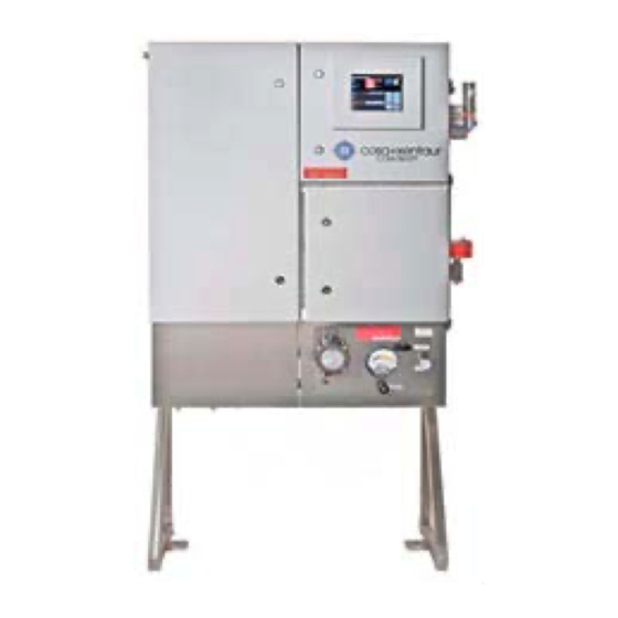
- Page 1 INSTALLATION, OPERATION MAINTENANCE MANUAL COSA 9610™ GENERAL PURPOSE & EXPLOSION PROOF Version: 1.4.2 Revision date: June 7 2019 CAL.01.D.9826...
- Page 2 COSA Instrument Corporation reserves the right to revise or to improve the design or specifications of the COSA 9610™ at any time and without notice.
-
Page 3: Table Of Contents
................... 16 TORAGE 2.3. P ................16 LACEMENT 2.3.1. General....................2.3.2. COSA 9610™ in general purpose execution (Type 01 & 02) ....2.3.3. COSA 9610™ in explosion proof execution (Type 01-Ex & 02-Ex) ..... 2.4. M ..............18 ECHANICAL ONNECTIONS 2.4.1. - Page 4 INSTALLATION, OPERATION AND MAINTENANCE MANUAL – COSA 9610™ 3.2. S ............. 25 TART P OF THE ONTROL 3.2.1. Description ..................3.2.2. Programming the measurement parameters..........3.2.3. Main screen ..................3.3. P ..............30 ROGRAMMING ENUS 3.3.1. Calibration Menu ................... 3.3.2.
-
Page 5: Introduction
Purpose of the analyzer The continuous COSA 9610™ analyzer determines online the Wobbe-index of a gas. The COSA 9610™ can be used both, as feed forward and feedback analyzer for gases mixing or as a feed forward analyzer for burning control. - Page 6 INSTALLATION, OPERATION AND MAINTENANCE MANUAL – COSA 9610™ 1.2.1. Oven with oxygen sensor The gas/air mixture is burnt catalytically in an oven, which is kept at 812ºC with a heating spiral. The temperature is maintained with temperature control using a K-type thermocouple.
-
Page 7: The Sample System (Scs)
INSTALLATION, OPERATION AND MAINTENANCE MANUAL – COSA 9610™ 1.2.2. The sample system (SCS) In the sample conditioning system (SCS), gas and air are mixed in a constant proportion, such that a small excess of air is present (± 2.5% oxygen) in the flue gas. The gas and air pressure, are equalized by a dome-loaded pressure reducer (or booster relay), where the gas pressure governs the air pressure. -
Page 8: Calibration Procedure
INSTALLATION, OPERATION AND MAINTENANCE MANUAL – COSA 9610™ 1.3. ALIBRATION ROCEDURE The analyzer can be calibrated in three different ways: • Single point calibration Only one calibration gas is used. The value of the gas is chosen middle of the measuring range. - Page 9 INSTALLATION, OPERATION AND MAINTENANCE MANUAL – COSA 9610™ The two-point calibration/validation procedure will be executed as followed: 1. Analyzer activates calibration/validation contact. 2. The procedure pauses for the specified “Calibration Start Delay” time for the external host to prepare for calibration/validation.
-
Page 10: Extended (Dual ) Range Option
INSTALLATION, OPERATION AND MAINTENANCE MANUAL – COSA 9610™ 1.4. XTENDED ANGE PTION 1.4.1. Operation When the measuring range of the analyzer is larger than 1150BTU/SCF, an extended range option is available which covers a Wobbe index of 2850.BTU/SCF. This is accomplished by adding a second gas-mixing orifice and selection valves to make changeover possible. -
Page 11: Pecifications
INSTALLATION, OPERATION AND MAINTENANCE MANUAL – COSA 9610™ 1.5. COSA 9610™ W PECIFICATIONS OBBE NDEX NALYZER 1.5.1. Analyzer performance Make Cosa Xentaur Corporation Service Natural gas, fuel-gas, biogas, etc. Ranges Wobbe index 0-2850 BTU/scf (0-95 MJ/Nm , span 0-1150 BTU/scf (40 MJ/Nm... -
Page 12: X-Purge Option
INSTALLATION, OPERATION AND MAINTENANCE MANUAL – COSA 9610™ 1.6 X-Purge option. The COSA 9610A™ Calorimeter is protected by a Pepperl & Fuchs X-purge unit: The purge Type X, EEx ‘px’ purge pressurization system protects general-purpose equipment mounted in a standard enclosure so that it can be located and operated in a hazardous area. - Page 13 INSTALLATION, OPERATION AND MAINTENANCE MANUAL – COSA 9610™ The EPV-X-Purge relief vent is separate and is mounted to the enclosure. The components of the X-Purge control unit are listed below: • EPCU mounted in an explosion/flameproof enclosure • I.S. user-interface with display and cable •...
- Page 14 • 30 SCFM @ 3.4” w.c., (850 l/min @ 86 mm w.c.) The COSA 9610™ uses the first setting of 5 SCFM @ 1.3” w.c. to establish the purge within the enclosures. This volume exchange and purge timing is factory set to 8mins, but can be re-configured to a different value if required by the Area Authority having jurisdiction at the installation site.
- Page 15 INSTALLATION, OPERATION AND MAINTENANCE MANUAL – COSA 9610™ Fixed Purge Time If the purge time must be held to a specific time, then this time is based on the known enclosure volume, number of volume exchanges, and flow rate through the vent. If the flow rate is below the required minimum, then the purging cycle will reset and will not start until the flow rate is above the selected rate.
- Page 16 INSTALLATION, OPERATION AND MAINTENANCE MANUAL – COSA 9610™ The intrinsic safety inputs activate the auxiliary relays, energize the Rapid Exchange valve, de-energize the enclosure contacts, and shut the system down, in addition to many more actions and outputs. Outputs There are (2) normally open dry contacts for the enclosure power that can be energized only after a successful purging and a minimum enclosure pressure is maintained.
-
Page 17: Installation
INSTALLATION, OPERATION AND MAINTENANCE MANUAL – COSA 9610™ 2. INSTALLATION 2.1. ENERAL Upon receipt and unpacking of the COSA 9610™ a visual inspection must be carried out to check for any visual damage, caused by transport. Any damage must be reported immediately to: COSA INSTRUMENT CORPORATION... -
Page 18: Cosa 9610™ In General Purpose Execution (Type 01 & 02)
The COSA 9610™ is supplied on a 304SS freestanding frame. This frame is to be placed on a flat surface (i.e. concrete slab). Two holes in the base of the frame enable the COSA 9610™ to be fixed to the floor . 2.3.3. -
Page 19: Mechanical Connections
• Location and amount of connections may vary depending on type and execution of the analyzer. See the project specific drawings of your order. • Tubing connections on the COSA 9610™ are Swagelok double ferrule compression type fittings for imperial sizes. -
Page 20: Sample Supply
2.4.3. Calibration gasses Calibration gas composition is depending on range and process gas. COSA INSTRUMENT can advise suitable compositions. For a single range analyzer, 2 calibration gasses (low and high value) are recommended. -
Page 21: Cosa 9610™ In Explosion Proof Execution
Supplied power must not exceed 250Vrms or 250Vdc. Power supply cable (ATEX). The COSA 9610™ used in ATEX approved applications requires the power supply to the unit to be controlled via the X-purge unit. To enable this the interposing relay in the breaker/marshaling cabinet must be connected to the control relays within the X-purge control unit. - Page 22 INSTALLATION, OPERATION AND MAINTENANCE MANUAL – COSA 9610™ Signal cables The COSA 9610™ has multiple input and output signals, which can be split in two groups, analog and digital signals. Both analog and digital signals are to be connected in the electronics enclosure.
-
Page 23: In Operation
1/4 turn with a suitable spanner. The supply and drainage tube can now be connected. Because the supply line is under pressure and has been closed off on the COSA 9610™ side, the connecting fittings can be squirted with soap in order to detect any possible leaks. -
Page 24: Opening Of Shut-Off Valves
INSTALLATION, OPERATION AND MAINTENANCE MANUAL – COSA 9610™ 3.1.3. Opening of shut-off valves Open the shut-off valve with identification plate "instrument air supply". 3.1.4. Setting of gas pressure reducer Turning the adjusting cap clockwise can raise the pressure of the gas pressure reducer. - Page 25 INSTALLATION, OPERATION AND MAINTENANCE MANUAL – COSA 9610™ Caution The adjusting screw is located in the gas compartment of the relay. When the insert is released, gas will escape. Be prepared before the relay is going to be adjusted, e.g. have the right equipment readily available, so the gas compartment has to be open for only a minimum of time.
-
Page 26: Start -U P Of The Control Unit
3.2.1. Description 3.2.2. Programming the measurement parameters Programming the COSA 9610™ is easy with the menu-controlled software. Menu can be navigated using the cursor keys. The key operations are: Menu navigation Change setting value or Enter... - Page 27 INSTALLATION, OPERATION AND MAINTENANCE MANUAL – COSA 9610™ Page 26 of 48...
- Page 28 INSTALLATION, OPERATION AND MAINTENANCE MANUAL – COSA 9610™ The lower right section displays the status of each digital input and output. The signal assignments are user-programmable. Explanation outputs Digital output driving low value calibration gas air cal gas 1 actuator...
- Page 29 INSTALLATION, OPERATION AND MAINTENANCE MANUAL – COSA 9610™ Menu Tree V2.3.0.0 Global Settings 1. Calibration 1. Start Calibration 2. Start Validation 1. Semi-automatic 3. Calibration gases 1. Semi-automatic 2. 1-point manual 4. Settings 1. Gas 1 Wobbe 2. 1-point manual 3.
- Page 30 INSTALLATION, OPERATION AND MAINTENANCE MANUAL – COSA 9610™ 4. Output (Analog & During Cal) 1. Channel A 2. Channel B 3. Channel C 4. Channel D Communication 1. Modbus 2. Serial 3. Ethernet 6. System 1. About 2. Date & Time 3.
-
Page 31: Programming Menus
INSTALLATION, OPERATION AND MAINTENANCE MANUAL – COSA 9610™ 3.3. ROGRAMMING ENUS The paragraph numbers correspond with the key sequence from the ‘menu tree’. In this way it is easy to see how a specific menu is reached. One exception is the measuring menu, this is reached from the main screen by either the ! or Enter key. -
Page 32: Operation Menu
INSTALLATION, OPERATION AND MAINTENANCE MANUAL – COSA 9610™ 3.3.2. Operation Menu Page 31 of 48... -
Page 33: Measurement Menu
INSTALLATION, OPERATION AND MAINTENANCE MANUAL – COSA 9610™ 3.3.3. Measurement Menu 3. Measurement 1. Wobbe 2. Calorific Value 3. CARI 4. Specific Gravity 5. Density 6. Residual Oxygen 7. Temperature 1. Oven 8. Pressure 1. Sample System 2. Sample System 9. -
Page 34: Output Menu
INSTALLATION, OPERATION AND MAINTENANCE MANUAL – COSA 9610™ 3.3.4. Output Menu Page 33 of 48... -
Page 35: Communications Menu
INSTALLATION, OPERATION AND MAINTENANCE MANUAL – COSA 9610™ 3.3.5. Communications Menu Submenus 1-3 with default communication settings: Page 34 of 48... - Page 36 INSTALLATION, OPERATION AND MAINTENANCE MANUAL – COSA 9610™ Page 35 of 48...
-
Page 37: System Menu
INSTALLATION, OPERATION AND MAINTENANCE MANUAL – COSA 9610™ 3.3.6. System Menu Passwords: USER: 1234 ADMIN: 9999 Page 36 of 48... -
Page 38: Display Menu
INSTALLATION, OPERATION AND MAINTENANCE MANUAL – COSA 9610™ Display Menu Page 37 of 48... -
Page 39: Reset Alarms Menu
INSTALLATION, OPERATION AND MAINTENANCE MANUAL – COSA 9610™ 3.3.7. Reset Alarms Menu Page 38 of 48... -
Page 40: Temperature Controlled Oven
INSTALLATION, OPERATION AND MAINTENANCE MANUAL – COSA 9610™ 3.4. EMPERATURE ONTROLLED 3.4.1. Furnace temperature control unit The zirconia cell must operate at a temperature above 600ºC. For optimal performance, a set-point temperature of 812ºC was chosen. The oven that serves as the heating device for the zirconia cell is made of a metal wire-wound heating element. -
Page 41: Adjustment Procedure Temperature Regulator
INSTALLATION, OPERATION AND MAINTENANCE MANUAL – COSA 9610™ NOTE: Set oven temp to 812ºC & sample system to 50ºC for standard units, 90ºC for mid-temp models 3.4.2. Adjustment procedure temperature regulator This procedure describes the setting of the temperature controller. -
Page 42: Preventive Maintenance
INSTALLATION, OPERATION AND MAINTENANCE MANUAL – COSA 9610™ 4. PREVENTIVE MAINTENANCE 4.1. EEKLY ONTHLY AINTENANCE 4.1.1. Compressor (optional) Checking for moisture. If the indicator on the drier has changed colour from light blue to lilac or pink, this indicates that the drier is saturated and is not working efficiently. If the indicator is discoloured, the supplier of the compressor should be contacted. -
Page 43: Annual Maintenance
INSTALLATION, OPERATION AND MAINTENANCE MANUAL – COSA 9610™ 4.3. NNUAL AINTENANCE • Check the calibration gas bottles for pressure. • Check the sample system for correct pressure. • Check the bypass flow meter for correct flow rate. • Replace the instrument air filters as required. - Page 44 INSTALLATION, OPERATION AND MAINTENANCE MANUAL – COSA 9610™ 4.4. ROUBLESHOOTING Breakdown -> fault report Test Action No air pressure -> tube fracture Replace tube flow alarm Measuring pressure behind Open valve for reducing valve reducing valve tagged “air supply” Increase output pressure No gas pressure ->...
-
Page 45: Replacement Of Residual Oxygen Sensor
INSTALLATION, OPERATION AND MAINTENANCE MANUAL – COSA 9610™ 4.5. EPLACEMENT OF ESIDUAL XYGEN ENSOR Before going any further make sure that the oven has been disconnected and cooled off so that no physical injury can occur caused by coming into contact with any parts which may still be hot. -
Page 46: Installation Drawing
INSTALLATION, OPERATION AND MAINTENANCE MANUAL – COSA 9610™ 5. INSTALLATION DRAWING Page 45 of 48... -
Page 47: Ordering Of Spare Parts
6. ORDERING OF SPARE PARTS All spare parts may be ordered quoting number and specification from: Installation and maintenance by trained personnel only. Please contact COSA Xentaur for a list of spare parts. COSA INSTRUMENT CORPORATION New York Texas Corporate Headquarters, Sales &... - Page 48 INSTALLATION, OPERATION AND MAINTENANCE MANUAL – COSA 9610™ Page 46 of 48...
-
Page 49: Certifications
INSTALLATION, OPERATION AND MAINTENANCE MANUAL – COSA 9610™ 7. CERTIFICATION 1. ATEX CERTIFICATE 2. US/CANADIAN CERTIFICATE 3. IECEx This product has been examined against the following standards 1. ATEX: EN 60079-0:2009 EN 60079-2:2007 EN 60079-11:2007 EN 60529 (+A1):2000 2. US/CANADA:... - Page 50 INSTALLATION, OPERATION AND MAINTENANCE MANUAL – COSA 9610™ Page 48 of 48...
- Page 51 INSTALLATION, OPERATION AND MAINTENANCE MANUAL – COSA 9610™ Page 48 of 48...
Need help?
Do you have a question about the 9610 and is the answer not in the manual?
Questions and answers